
1. Introduction
2. Configuration
- 2.1 Configuration overview
- 2.2 System readiness
- 2.3 Configuration tools
- 2.4 How to configure
- 2.5 Application specific configuration
- 2.6 Detailed transmitter setup
- 2.7 Configure using Bluetooth® wireless technology
- 2.8 Diagnostics overview
- 2.9 Performing transmitter tests
- 2.10 Configuring Burst mode
- 2.11 Using High Speed Sensor Response Time (option P6)
3. Hardware installation
4. Electrical installation
- 4.1 Overview
- 4.2 Install LCD display
- 4.3 Configuring transmitter security
- 4.4 Move Alarm switch
- 4.5 Electrical considerations
5. Relay switches (Transmitter output code S)
- 5.1 Relay terminal block components
- 5.2 How relay switches work
- 5.3 Relay wiring
- 5.4 Relay power
- 5.5 Relay configuration
- 5.6 Commissioning a transmitter with relay switches
- 5.7 Relay switch operation examples
- 5.8 Relay tests
- 5.9 Relay diagnostics
6. Operation and maintenance
- 6.1 Overview
- 6.2 Recommended calibration tasks
- 6.3 Calibration overview
- 6.4 Trimming pressure signal
- 6.5 Trimming the analog output
- 6.6 Relay maintenance and operation (with output protocol code S)
7. Troubleshooting
- 7.1 Troubleshooting overview
- 7.2 Diagnostic messages
- 7.3 Disassembling the transmitter
- 7.4 Reassembly procedures
8. Safety Instrumented Systems (SIS)
- 8.1 Rosemount 4051S safety certified identification
- 8.2 Installation in Safety Instrumented Systems (SIS) applications
- 8.3 Configuring in Safety Instrumented Systems (SIS) applications
- 8.4 Damping
- 8.5 Alarm and saturation levels
- 8.6 Safety Instrumented Systems (SIS) operation and maintenance
- 8.7 Inspection
A. Reference data
B. Device Driver (DD) menu trees
C. Quick Service buttons
Safety information
warning
Read this document before working with the product. For personal and system safety and for optimum product performance, ensure that you thoroughly understand the contents before installing, using, and maintaining the product.
Failure to follow safe installation and servicing guidelines could result in death or serious injury.
Ensure the transmitter is installed by qualified personnel and in accordance with applicable code of practice. Use the transmitter only as specified in the product manual. Failure to do so may impair the protection provided by the transmitter.
Repair, e.g. substitution of components, etc. may jeopardize safety and is under no circumstances allowed. Unauthorized changes to the product are strictly prohibited, as they may unintentionally and unpredictably alter performance and jeopardize safety. Unauthorized changes that interfere with the integrity of the welds or flanges, such as making additional perforations, compromise product integrity and safety. Equipment ratings and certifications are no longer valid on any products that have been damaged or modified without the prior written permission of Emerson. Any continued use of product that has been damaged or modified without the written authorization is at the customer’s sole risk and expense.
Explosions
Explosions could result in death or serious injury.
In an explosion-proof/flameproof installation, do not remove the transmitter covers when power is applied to the transmitter. Installation of this transmitter must be in accordance with the appropriate local, national, and international standards, codes, and practices. Review the hazardous locations certifications in the Rosemount 4051S Pressure Transmitters Quick Start Guide for any restrictions associated with a safe installation. Before connecting a field communicator in an explosive atmosphere, ensure that the instruments are installed in accordance with intrinsically safe or non-incendive field wiring practices.
Process leaks
Process leaks may cause harm or result in death.
Install and tighten process connectors before applying pressure. Do not remove while in operation.
Electrical shock
Electrical shock can result in death or serious injury.
Avoid contact with the leads and terminals. High voltage that may be present on leads can cause electrical shock. Ensure the power to the transmitter is off and the lines to any other external power source are disconnected or not powered while wiring the transmitter. Ensure the wiring is suitable for the electrical current and the insulation is suitable for the voltage, temperature, and environment.
Replacement equipment
The use of replacement equipment or spare parts not approved by Emerson may reduce the pressure retention or other safety capabilities of the transmitter and may lead to dangerous or unsafe or dangerous conditions.
Use only bolts, replacement equipment, or other spare parts supplied or approved by Emerson.
When cover is removed, protect the interior of the transmitter from external contamination exceeding that of a Pollution Degree 2 environment.
warning
Physical access
Unauthorized personnel may potentially cause significant damage to and/or misconfiguration of end users’ equipment. This could be intentional or unintentional and needs to be protected against.
Physical security is an important part of any security program and fundamental in protecting your system. Restrict physical access by unauthorized personnel to protect end users’ assets. This is true for all systems used within the facility.
1. Introduction
1.1 Models covered
The following Rosemount 4051S Transmitters are covered by this manual:
- Rosemount 4051S Coplanar™ Pressure Transmitter
- Measures differential and gauge pressure up to 2,000 psi (137.9 bar).
- Measures absolute pressure up to 4,000 psia (275.8 bar).
- Rosemount 4051S In-Line Pressure Transmitter
- Measures gauge pressure up to 10,000 psig (689.5 barg) and absolute pressure up to 10,000 psia (689.5 bar).
- Rosemount 4051SLT Level Transmitter
- Measures level up to 300 psi (20.7 bar).
- Rosemount 4051SF Differential Pressure (DP) Flow Meters
- Measures flow in line sizes from ½ to 96 in. (13 to 2,438 mm).
1.2 Product recycling/disposal
Consider recycling equipment and packaging.
Dispose of the product and packaging in accordance with local and national legislation/regulations.
2. Configuration
2.1 Configuration overview
This section provides instructions for tasks that must be performed prior to device installation, during commissioning, and after installation.
Instructions for configuration by the following methods are included:
- Communication device, such as AMS Trex
- HART® host, such as AMS Device Manager
- AMS Device Configurator Bluetooth® app
- Quick Service buttons
2.2 System readiness
If using HART®-based control or asset management systems, confirm the HART capability of such systems prior to commissioning and installation. Not all systems can communicate with HART Revision 7 devices.
- Verify that the latest device driver (DD/DTM™) is loaded on your systems to ensure proper communications.
- Download the latest DD at Software & Drivers or FieldCommGroup.org
2.3 Configuration tools
Set up the transmitter before or after mounting it by wiring it to a power supply and a configuration device as shown in Figure 2-1.
Configure the transmitter either before or after installation. To ensure that all transmitter components are in working order prior to installation, configure the transmitter on the bench using the applicable communication device and power supply.
See Figure 2-1 for more information on how to wire the power supply and attach leads from a communication device.
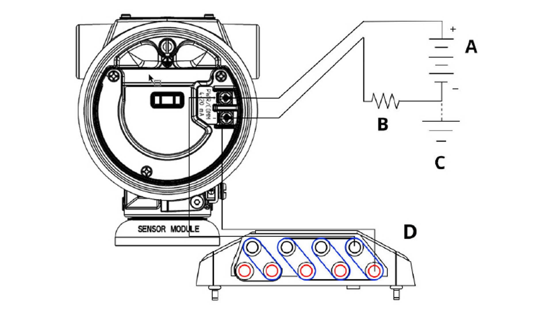
Figure 2-1: Power Supply and Communicator Wiring
A. Power supply
B. Resistor
C. Ground
D. Communicator wiring
note
You do not need the resistor if you are connected in one of the following ways:
- AMS Trex (HART + power)
- AMS Device Configurator Bluetooth® app
- Quick Service buttons
AMS Device Manager | ≥ 17.4 Vdc | ≥ 250 Ω |
AMS Trex (HART®) | ≥ 17.4 Vdc | ≥ 250 Ω |
AMS Trex (HART + pwr) | None | None |
AMS Device Configurator Bluetooth app | 11.5 Vdc | None |
Quick Service buttons | 11.5 Vdc | None |
For more detailed information about AMS Trex, see AMS Trex Device Communicator.
It is critical that the latest device drivers (DDs) are loaded onto the communication device to ensure full functionality.
2.4 How to configure
Each unique application of the Rosemount 4051S may require different steps to commission and configure the transmitter.
This section provides an overview of the procedures to perform common configuration tasks on your transmitter.
note
If either the hardware Security switch or the software Security setting is On, it is not possible to configure the transmitter.
Before sending or requesting data that would disrupt the loop or change the output of the transmitter, set the process application loop to Manual control.
note
The configuration device will prompt you to set the loop to Manual when necessary. The prompt is only a reminder; acknowledging this prompt does not set the loop to Manual. You must set the loop to Manual control as a separate operation.
2.5 Application specific configuration
With the flow rate configuration, you can create a relationship between the pressure units and user-defined flow units. By defining a pressure at a specific flow rate, the transmitter will perform a square root extraction to convert the pressure reading to a linear flow rate output.

Flow rate configuration includes the following parameters:
Flow Units |
User-specified units for flow rate |
Entered Flow Rate |
User-specified flow rate |
Pressure at Flow Rate |
User-specified pressure at the entered flow rate(1) |
(1) You can use the DP Flow Sizing and Selection Tool to help you establish the relationship between pressure and flow.
Configure for flow rate using a communication device
Procedure
Go to Device Settings → Output → Flow → Setup → Configure Flow
Configuring Low Flow Cut-off
Emerson highly recommends using the Low Flow Cut-off function to have a stable output and avoid problems due to process noise at a low flow or no flow condition.
There are two key definitions to aid in understanding Low Flow Cut-off:
Pressure cut-off value |
The pressure at which the field device will stop measuring the flow rate. If the measured pressure is less than the pressure cut-off value, the device will calculate the flow rate to be zero. |
Pressure cut-in value |
The pressure at which the field device will begin measuring the flow rate. If the measured pressure is more than the cut-in value, the device will begin measuring flow rate. |
Configure Low Flow Cut-off using a communication device
Procedure
Go to Device Settings → Output → Flow → Setup → Low Flow Cut-off
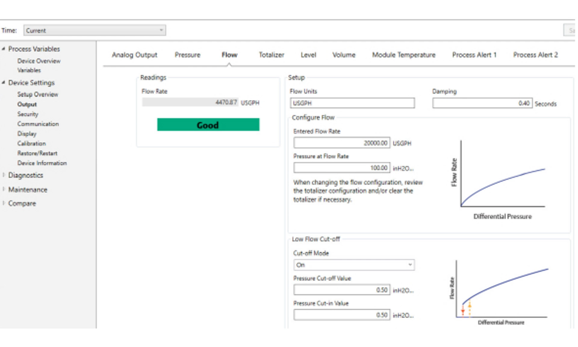
Configuring for flow rate example
Use a differential pressure transmitter in conjunction with an orifice plate in a water flow application where the full-scale flow rate is 20,000 US gallons per hour with a differential pressure of 100 inH2O at 68 °F. The pressure cut-off and pressure cut-in values for the Low Flow Cut-off will be set to 0.5 inH2O at 68 °F.
Based on this information, the configuration would be:
Flow Rate Units | USGPH |
Entered Flow Rate | 20,000 USGPH |
Pressure at Flow Rate | 100 inH2O at 68 °F |
Low Flow Cut-off | Cut-off mode: On |
Pressure Cut-off Value | 0.5 inH2O at 68 °F |
Pressure Cut-in Value | 0.5 inH2O at 68 °F |
Figure 2-3: AMS Configuration Screen for Flow Rate Example
2.6 Detailed transmitter setup
In normal operation, the transmitter drives the output in response to pressure from the lower and upper trim points. If the pressure goes outside of the sensor limits, or if the output would be beyond the saturation points, the output will be limited to the associated saturation point.
The Rosemount 4051S Transmitter automatically and continuously performs self-diagnostic routines. If the self-diagnostic routines detect a failure, the transmitter drives the output to configured alarm value based on the position of the Alarm switch.
Low | 3.9 mA | ≤ 3.725 mA |
High | 20.8 mA | > 22.5 mA |
Low | 3.8 mA | ≤ 3.575 mA |
High | 20.5 mA | > 22.5 mA |
Low | 3.67 - 3.90 mA | 3.57 - 3.80 mA |
High | 20.1 - 22.9 mA | 20.2 - 23.0 mA |
- Low alarm level must be at least 0.1 mA less than the low saturation level.
- High alarm level must be at least 0.1 mA higher than the high saturation level.
Related information
Move Alarm switch
Configure Alarm and Saturation Values using a communication device
Procedure
Go to Device Settings → Setup Overview → Alarm and Saturation Values → Configure Alarm and Saturation Values.

2.7 Configure using Bluetooth® wireless technology
Procedure
1. Launch AMS Device Configurator.
See AMS Device Configurator for Emerson Field Devices.
2. Select the device you want to connect to.
3. On first connection, enter the Unique Identifier (UID) and Key for selected device and select the appropriate role.
4. At the top left, select the menu icon to navigate to the desired device menu.
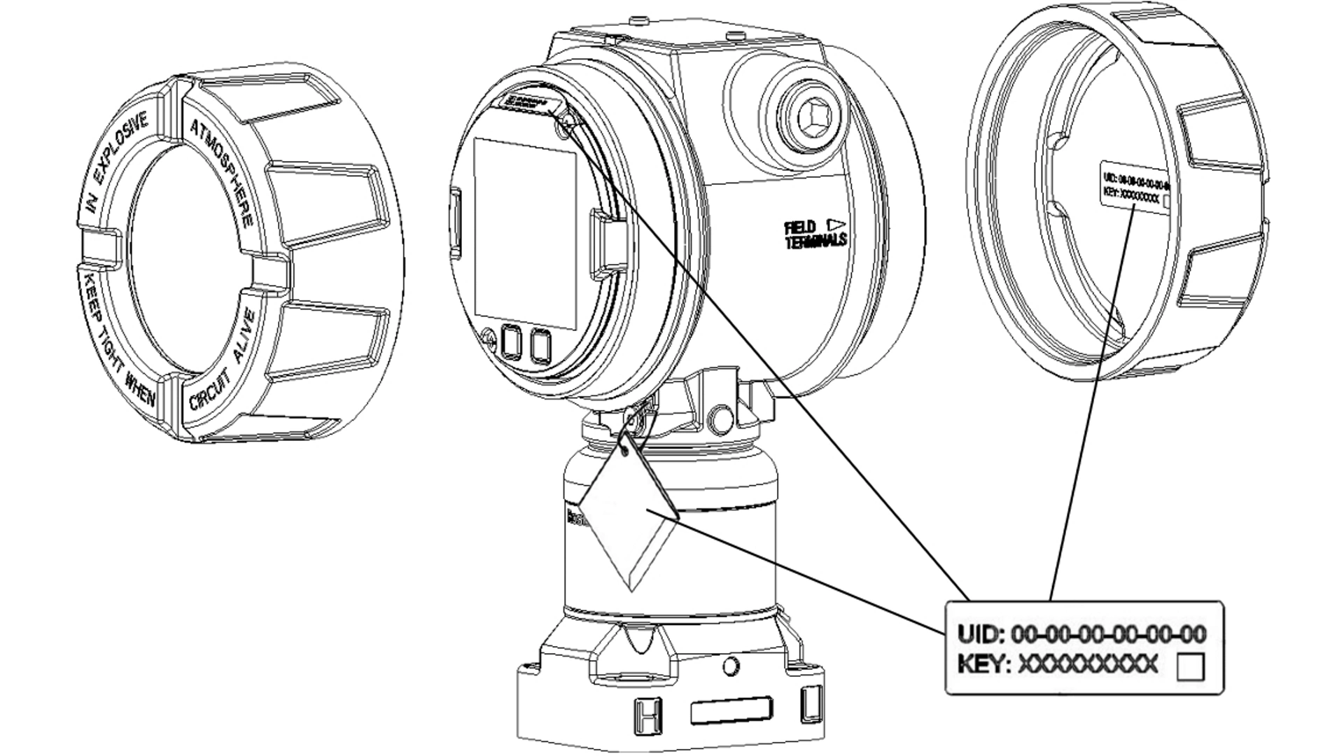
Bluetooth® Unique Identifier (UID) and Key
The UID is the identification number unique to the Bluetooth radio on the device.
The UID will be advertised when Bluetooth functionality is enabled on the output board. The Key is the required passkey to access the device. The information is only available in the tags located as shown in Figure 2-10. Emerson does not retain copies of this
information.
You can find the UID and Key in the following locations:
- Disposable paper tag attached to the device
- Label inside the terminal block cover
- Label on the display unit
Figure 2-10: Bluetooth Security Information
2.8 Diagnostics overview
The diagnostics function on the Rosemount 4051S Pressure Transmitter provides operators with a method to proactively identify and alert to common process upsets.
note
The diagnostics and service functions in this section are primarily for use after field installation.
Enabling these features reduces the potential of a process shutdown or failure, which could be a safety concern or cause environmental damage. The diagnostic alerts are available from multiple sources, including all asset management systems. These diagnostics provide insight into the processes supported by operators beyond the basic process variable. This section outlines overviews of each diagnostic as well as the steps for configuration.
You can use the Loop Integrity diagnostic to detect issues that may jeopardize the integrity of the electrical loop.
Some examples are:
- Water entering the wiring compartment and making contact with the terminals
- An unstable power supply nearing end of life
- Heavy corrosion on the terminals
The technology is based on the premise that once a transmitter is installed and powered up, the electrical loop has a baseline characteristic that reflects the proper installation. If the transmitter terminal voltage deviates from the baseline and outside the user configured threshold, the transmitter can generate a HART Status Alert or Analog Output Alarm.
To use the diagnostic, you must first create a baseline characteristic for the electrical loop after installing the transmitter.
The loop is automatically characterized during configuration. The diagnostic creates a linear relationship for expected terminal voltage values along the operating region from 4-20 mA.
See Figure 2-11.
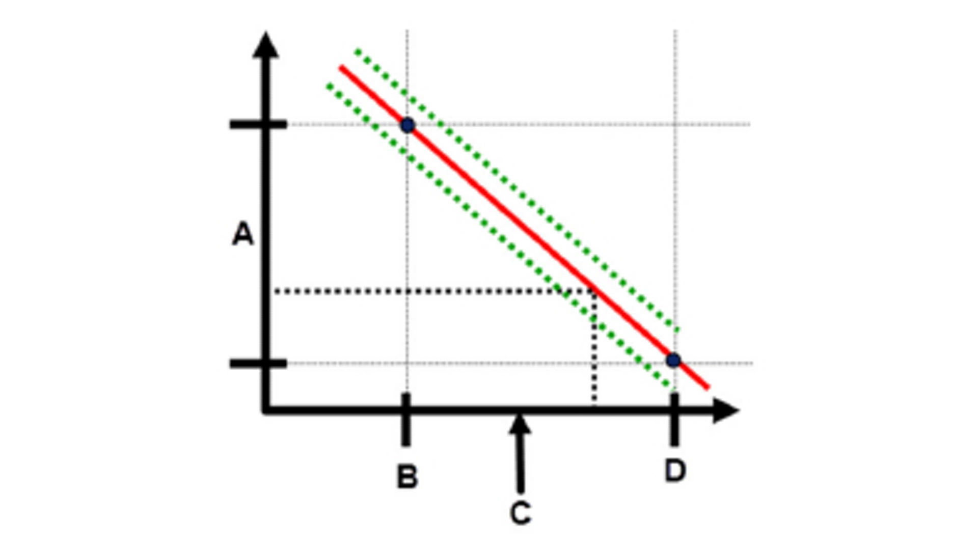
Figure 2-11: Baseline Operating Region
A. Terminal voltage
B. 4 mA
C. Output current
D. 20 mA
Emerson ships the transmitter with the Loop Integrity diagnostic off as a default setting and without any loop characterization performed. Once the transmitter is installed and powered up, you must configure the Loop Integrity diagnostic, which performs a loop characterization, for the diagnostic to function.
When you complete the steps for configuring Loop Integrity, the transmitter will check to see if the loop has sufficient power for proper operation. The transmitter will then drive the analog output to both 4 and 20 mA to establish a baseline and determine the maximum allowable voltage deviation. Once this is complete, enter a sensitivity value called Voltage Deviation Limit, and a check is in place to ensure the value is valid.
Once you have characterized the loop and set the Voltage Deviation Limit, the Loop Integrity diagnostic begins to actively monitor the electrical loop for deviations from the baseline. If the voltage has changed relative to the expected baseline value, exceeding the configured Voltage Deviation Limit, the transmitter can generate a HART Status Alert or Analog Output Alarm, depending on what is selected during configuration.
note
The Loop Integrity diagnostic in the Rosemount 4051S Pressure Transmitter monitors and detects changes in the terminal voltage from expected values to detect common failures. It is not possible to predict and detect all types of electrical failures on the 4-20 mA output. Therefore, Emerson cannot absolutely warrant or guarantee that the Loop Integrity diagnostic will accurately detect failures under all circumstances.
Terminal Voltage
This field shows the current terminal voltage value in volts.
The Terminal Voltage is a dynamic value and is directly related to the mA output value.
Voltage Deviation Limit
Set the Voltage Deviation Limit large enough that expected voltage changes do not cause false failures.

Figure 2-12: Voltage Deviation Limit
A. Voltage Deviation Limit
B. Terminal voltage
C. Alert
note
Changes in electrical loop
Severe changes in the electrical loop may inhibit HART® communication or the ability to reach alarm values. Therefore, Emerson cannot absolutely warrant or guarantee that the correct Failure alarm level (High or Low) can be read by the host system at the time of annunciation.
Resistance
This value is the calculated resistance of the electrical loop (in ohms) measured during the Loop Characterization procedure.
Changes in the resistance may occur due to changes in the physical condition of the loop installation. You can compare baseline and previous baselines to see how much resistance has changed over time.
Power Supply
This value is the calculated power supply voltage of the electrical loop (in volts) measured during the configuration procedure.
Changes in this value may occur due to degraded performance of the power supply. You can compare baseline and previous baselines to see how much the power supply has changed over time.
Loop Integrity Notification mode
When you configure Loop Integrity, you can select one of three different Notification modes.
- Disable Diagnostic
- HART® Status Alert
- Analog Output Alarm
The HART Status Alert setting causes an unlatched alarm, meaning that if the voltage deviation returns to within the set Voltage Deviation Limit, the alert will be cleared from the active alerts. However, the event will still be recorded in the Diagnostic log.
Note
You must configure Loop Integrity after installing the transmitter for the first time or after intentionally altering electrical loop characteristics. Emerson does not recommend the Loop Integrity diagnostic for transmitters operating in Multi-drop mode. Examples include:
- Modifying power supply level or loop resistance of the system
- Changing the terminal block on the transmitter
- Adding the Wireless THUM™ Adapter to the transmitter
Configure Loop Integrity diagnostic using a communication device
Prerequisites
The transmitter must be installed in an active running process to successfully configure the diagnostic. Ensure that the device is in this state prior to configuring.
Procedure
1. Go to Diagnostics → Alerts → Loop Integrity Diagnostic → Configure Loop Integrity
2. After the loop characterization has completed, enter the desired Voltage Deviation Limit.
3. Select a Notification Mode:
- Disable Diagnostic
- HART® Status Alert
- Analog Output Alarm
4. Once the diagnostic is configured, you can adjust the Notification Mode and Voltage Deviation Limit.
2.9 Performing transmitter tests
If you repair or replace the transmitter electronics board, sensor module, or display, verify the transmitter alarm level before returning the transmitter to service. This is useful in testing the reaction of the control system to a transmitter in an Alarm state, thus ensuring that the control system recognizes the alarm when activated.
To verify the transmitter alarm values, perform a loop test and set the transmitter output to the alarm value.
2.10 Configuring Burst mode
Burst mode is compatible with the analog signal. Because the HART® protocol features simultaneous digital and analog data transmission, the analog value can drive other equipment in the loop while the control system is receiving digital information.
Burst mode applies only to the transmission of dynamic data and does not affect the way other transmitter data is accessed. However, when activated, Burst mode can slow down communication of non-dynamic data to the host by 50 percent.
The transmitter accesses information other than dynamic transmitter data through the normal poll/response method of HART communication. A communication device or the control system may request any of the information that is normally available while the transmitter is in Burst mode. Between each message sent by the transmitter, a short pause allows the communication device to initiate a request.
Message content options:
Cmd 1 |
Read Primary Variable |
Cmd 2 |
Read Percent Range/Current |
Cmd 3 |
Read Dynamic Variables/Current |
Cmd 9 |
Read Device Variables with Status |
Cmd 33 |
Read Device Variables |
Cmd 48 |
Read Additional Device Status |
Trigger mode options:
- Continuous
- Rising
- Falling
- Windowed
- On change
Note
You can also opt to use advanced burst mode capability.
note
Consult host system manufacturer for Burst mode requirements.
Configure Burst mode using a communication device
Procedure
Go to Device Settings → Output (or Communication) → HART → Burst Mode Configuration
2.11 Using High Speed Sensor Response Time (option P6)
The High Speed Response option is available with option code P6. This option will change the transmitter response time to 40 ms.
The overall update rate will be dependent on Damping settings and if communication is via analog or HART®.
3. Hardware installation
3.1 Overview
The information provided in this section covers installation considerations for the Rosemount 4051S with HART® protocol.
Emerson ships the Rosemount 4051S Pressure Transmitters Quick Start Guide with every transmitter to provide basic installation, wiring, and start-up procedures.
Dimensional drawings for each 4051S Pressure Transmitter variation and mounting configuration are included in Type 1 Drawings.
Note
The following sections contain installation instructions for many optional features. Only follow a section's directions if the transmitter being installed comes with the features described.
Related information
Disassembling the transmitter
Reassembly procedures
3.2 Considerations
Measurement accuracy depends upon proper installation of the transmitter and impulse piping. Mount the transmitter close to the process and use a minimum amount of piping to achieve best accuracy. Keep in mind the need for easy access, personnel safety, practical field calibration, and a suitable transmitter environment. Install the transmitter to minimize vibration, shock, and temperature fluctuation.
3.3 Installation procedures
Mount the process flanges with sufficient clearance for process connections. For safety reasons, place the drain/vent valves so the process fluid is directed away from possible human contact when the vents are used. In addition, consider the need for a testing or calibration input.
4. Electrical installation
4.1 Overview
The information in this section covers installation considerations for the Rosemount 4051S Transmitter.
The Rosemount 4051S Pressure Transmitters Quick Start Guide is shipped with every transmitter to describe pipe-fitting, wiring procedures, and basic configuration for initial installation.
4.2 Install LCD display
Emerson ships the transmitters ordered with the graphical LCD display option with the display installed.
To install the display on an existing transmitter:
Prerequisites
Small instrument screwdriver
Procedure
Carefully align the desired display connectors with the electronics board connector.
If the connectors don't align, the display and electronics board are not compatible.
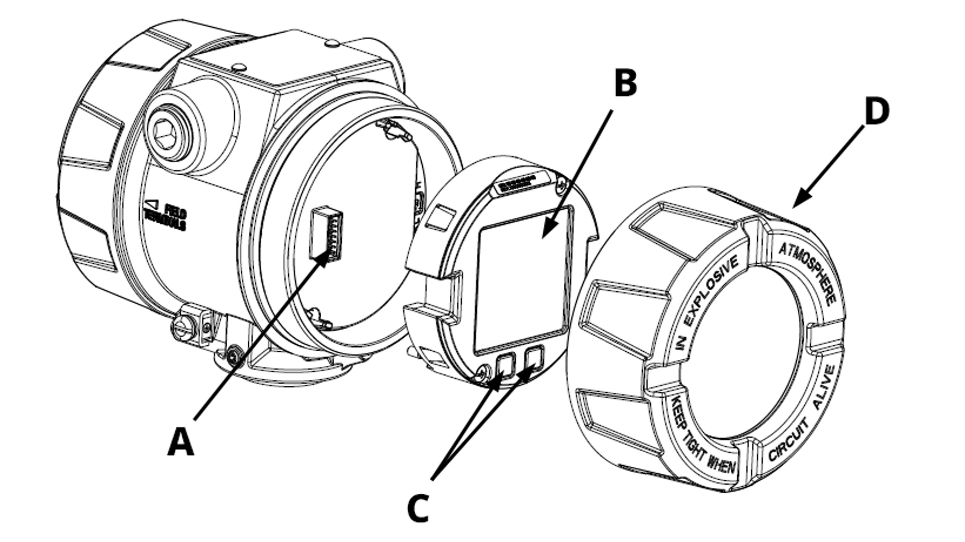
Figure 4-1: LCD Display Assembly
A. Interconnecting pins
B. Display
C. Quick Service buttons
D. Cover
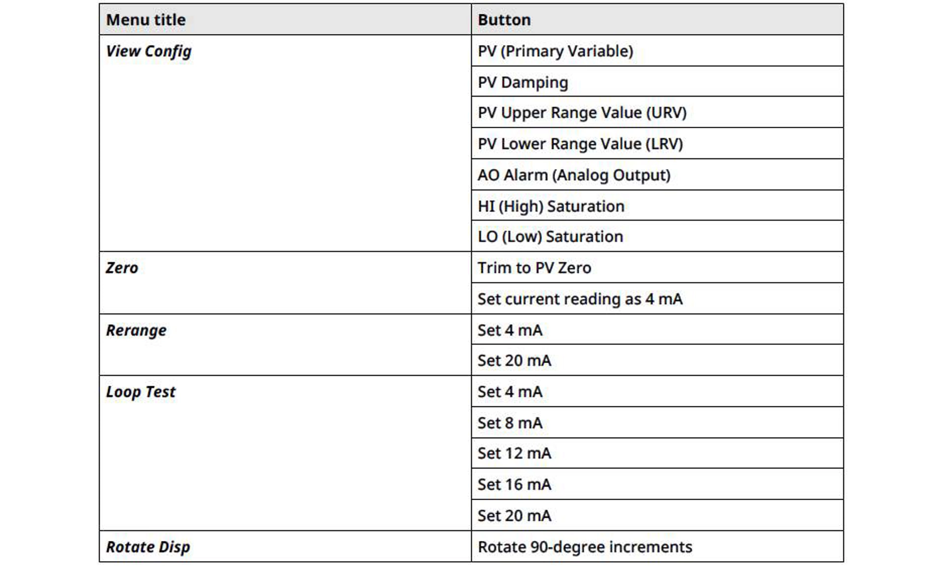
Rotate Display
If you need to, you can rotate the graphical LCD display in 90-degree increments using software.
You can access this feature with any configuration tool or with the Quick Service buttons.
4.3 Configuring transmitter security
There are two ways to manage security:
- Hardware security switches
- Software security switches
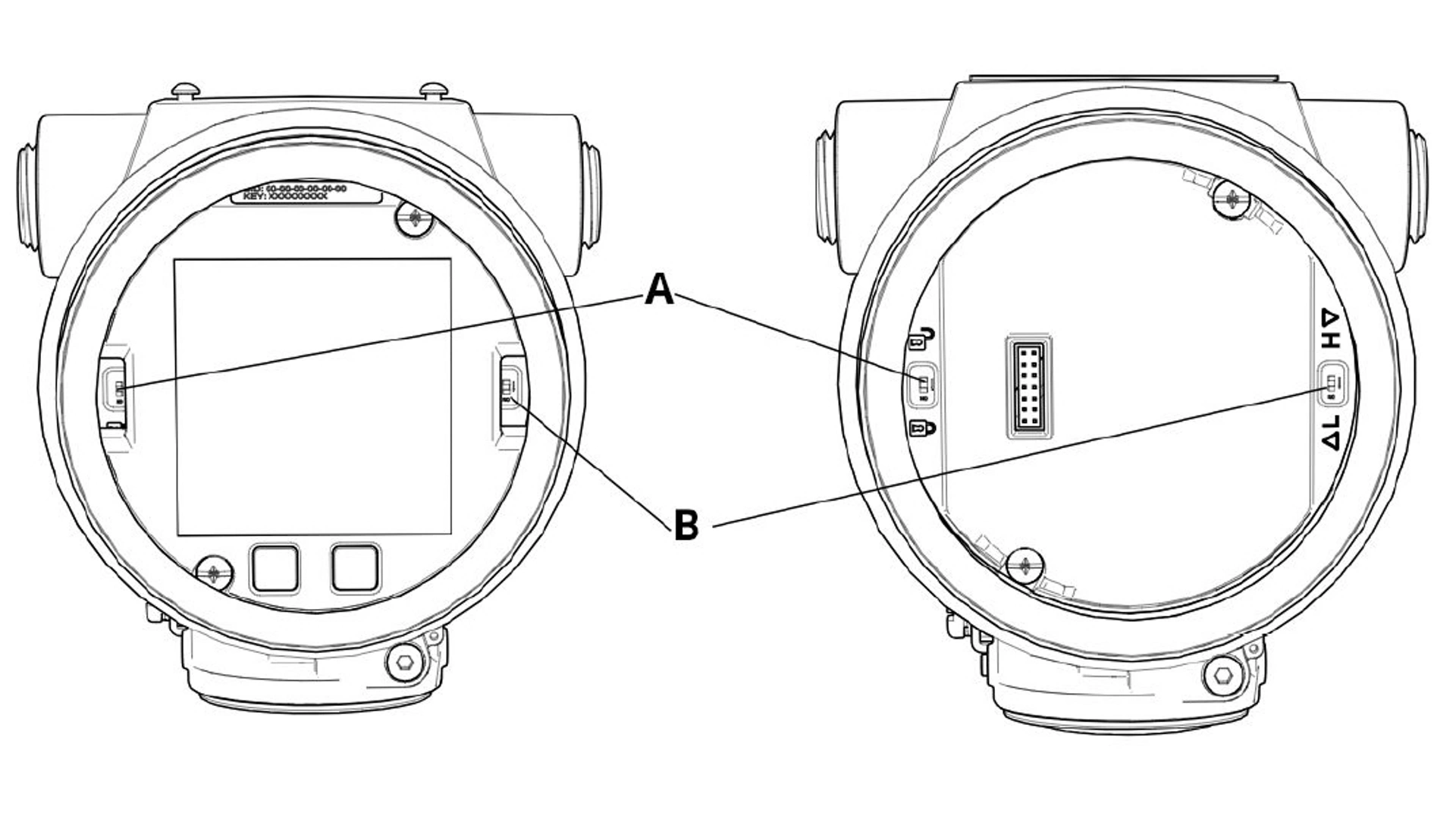
Figure 4-2: Electronics Board
A. Security switch
B. Alarm switch
You can enable the Security switch to prevent changes to the transmitter configuration data.
If you set the Security switch to Locked, the transmitter will reject any configuration requests sent via HART®, Bluetooth®, or Quick Service buttons, and it will not modify configuration data.
See Figure 4-2 for the location of the Security switch.
Procedure
1. If the transmitter is installed, secure the loop and remove power.
warning
Explosions
Explosions could result in death or serious injury.
In an explosion-proof/flameproof installation, do not remove the transmitter covers when power is applied to the transmitter.
2. Remove the housing cover opposite the field terminal side.
warning
Do not remove the instrument cover in explosive atmospheres when the circuit is live.
3. Use a small screwdriver to slide the switch to the Lock position.
4. Reattach transmitter housing cover.
Emerson recommends tightening the cover until there is no gap between the cover and housing to comply with explosion-proof requirements.
4.4 Move Alarm switch
There is an Alarm switch on the electronics board to set whether the transmitter will drive to the configured high or low value when in an alarm state.
For switch location, see Figure 4-2.
Procedure
1. Set loop to Manual and remove power.
warning
Explosions
Explosions could result in death or serious injury.
In an explosion-proof/flameproof installation, do not remove the transmitter covers when power is applied to the transmitter.
2. Remove transmitter housing cover.
3. Use a small screwdriver to slide switch to desired position.
4. Replace transmitter cover.
warning
The cover must be fully engaged to comply with explosion-proof requirements.
Install cover jam screw
For transmitter housings shipped with a cover jam screw, install the screw after wiring and powering up the transmitter.
The cover jam screw is intended to prevent removing the transmitter cover in flameproof environments without using tools.
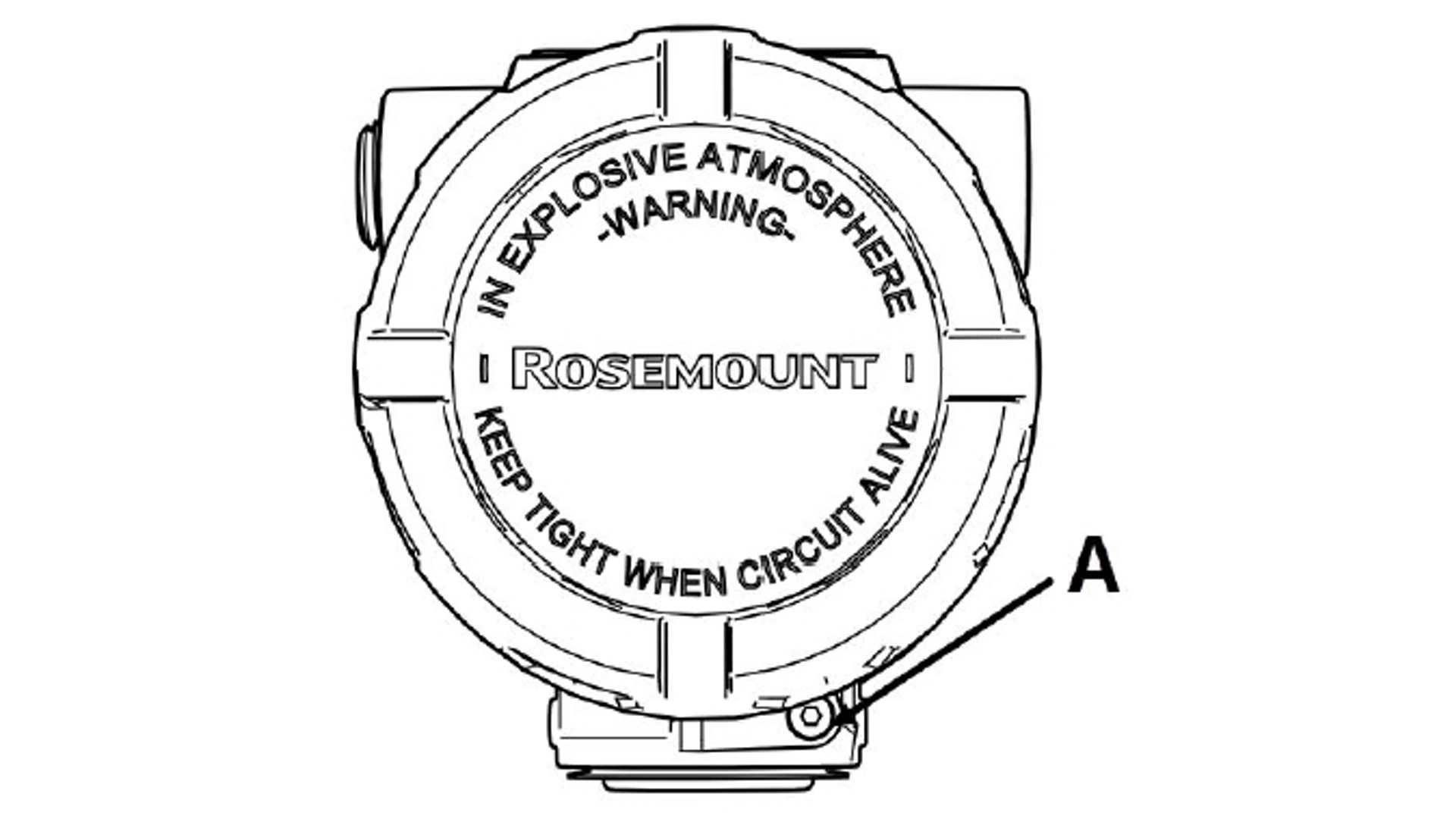
Figure 4-3: Cover Jam Screw
A. Cover jam screw
Procedure
1. Verify the cover jam screw is completely threaded into the housing.
2. Install the transmitter housing cover and verify that the cover is tight against the housing.
3. Using an M4 hex wrench, loosen the jam screw until it contacts the transmitter cover.
4. Turn the jam screw an additional ½ turn counterclockwise to secure the cover.
note
Applying excessive torque may strip the threads.
5. Verify the cover cannot be removed.
4.5 Electrical considerations
warning
Electrical shock
Electrical shock can result in death or serious injury.
Ensure all electrical installation is in accordance with national and local code requirements.
Do not run signal wiring in conduit or open trays with power wiring or near heavy electrical equipment.
note
Transmitter damage
If all connections are not sealed, excess moisture accumulation can damage the transmitter.
Mount the transmitter with the electrical housing positioned downward for drainage. To avoid moisture accumulation in the housing, install wiring with a drip loop and ensure the bottom of the drip loop is mounted lower than the conduit connections of the transmitter housing.
Figure 4-4 shows recommended conduit connections.
Figure 4-4: Conduit Installation Diagrams
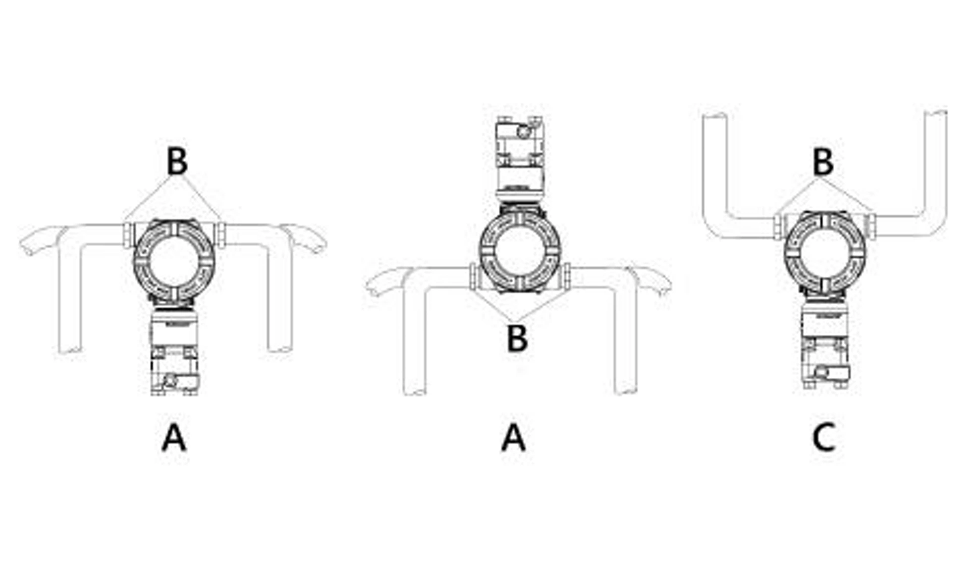
A. Possible conduit line positions
B. Sealing compound
C. Incorrect
5. Relay switches (Transmitter output code S)
The Rosemount 4051S Pressure Transmitter supports two integral high voltage, high current single pole double throw (SPDT) switches connected directly to the transmitter. An integral relay switch takes the traditional pressure relay switch and embeds it into the transmitter.
On the 4051S, the relay switches are in the transmitter terminal block. Use the Process Alert function to configure the relays, which are controlled by the transmitter measurement.
Depending on how the relay is wired, this will either break or complete the circuit of a connected power load. Each of the two relays has a normally closed (NC) terminal, normally open (NO) terminal, and common (COM) terminal. There is a positive and negative power terminal that powers the switch separately from the positive and negative power terminal that powers the transmitter.
The following sections cover more details on the switch operation, wiring, and configuration.
Related information
Relay maintenance and operation (with output protocol code S)
5.1 Relay terminal block components
If you order the Rosemount 4051S Pressure Transmitter with relay switches, it will come with a different terminal block from the standard transmitter.
The two relay switches are integrated directly into the terminal block as shown in Figure 5-1.
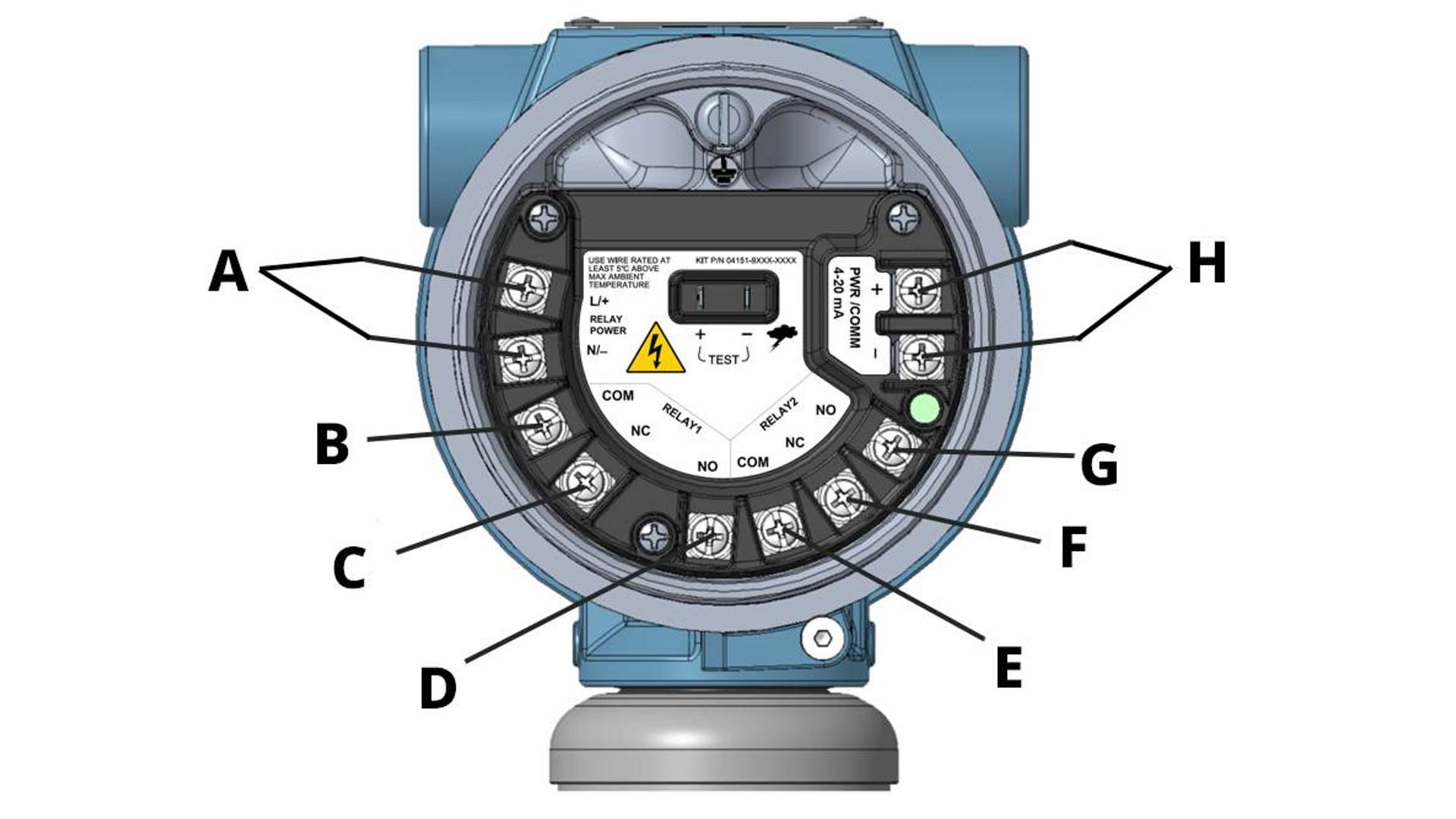
Figure 5-1: Relay Terminal Block
A. Relay power terminals
B. Common terminal for Relay switch 1
C. Normally closed terminal for Relay switch 1
D. Normally open terminal for Relay switch 1
E. Common terminal for Relay switch 2
F. Normally closed terminal for Relay switch 2
G. Normally open terminal for Relay switch 2
H. Transmitter power terminals
5.2 How relay switches work
This section explains how the relay switches work internally on the Rosemount 4051S Pressure Transmitter.
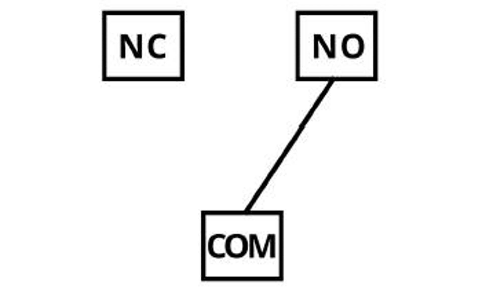
The switch is an electromechanical relay consisting of three terminals: Common terminal (COM), Normally Closed terminal (NC), and Normally Open terminal (NO). The switch is always connected at COM and either NC or NO.
When the switch has no power or connections, it defaults to its “out of the box” state. This is also the state it will revert to during a power failure. In this state, the physical switch will be positioned between the COM terminal and the NC terminal. Additionally, the switch's configuration during an active alert will determine what the configured position is during an Off state.
When the switch is Energized, it is positioned between the COM and user-configured terminal, either NO or NC. Based on the configured Process Alerts, the transmitter tells the switch when to toggle between Off and Energized.
The three states the switch can be in are:
Normal Operating state |
This refers to the state that the relay is in when the Process Alert is not triggered. This state is user-defined via the Process Alert configuration. |
Alert state |
This refers to the state that the relay will go to when the Process Alert is triggered. This state is user-defined via the Process Alert configuration. |
Fail state |
This refers to the state that the relay will go to when a Failure mode is triggered. This state is always COM to NC. |
5.3 Relay wiring
note
Due to the high voltage capabilities of the relay switch, Emerson provides a cover for the terminals.
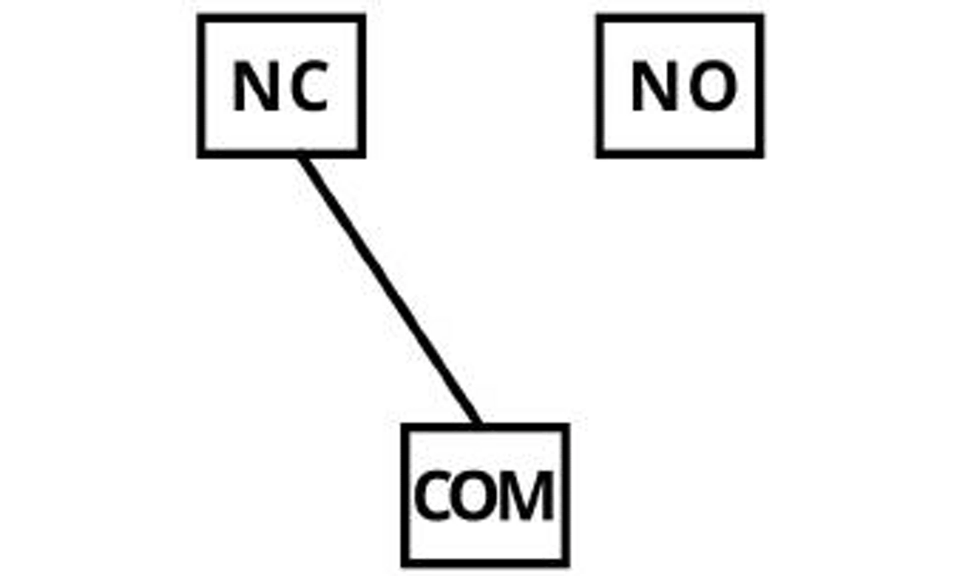
When the switch is in a Fail state, it will always be connected between the Common (COM) and Normally Closed (NC) terminals. The way the relay circuit is wired determines how it will operate when the switch is in a Fail state. If the wires are connected to COM and NC, then the circuit will be closed when in a Fail state. If the wires are connected to COM and NO, then the circuit will be open when in a Fail state. This is where the terms Normally Closed and Normally Open come from. The terminals that wires are connected to will determine if the circuit is open or closed in a Fail state. the following figures are examples of relay wiring for Normally Open vs. Normally Closed with powered load. The wiring between the transmitter and equipment is green.
Figure 5-2: Normally Open Wiring (left) and Normally Closed Wiring (right)
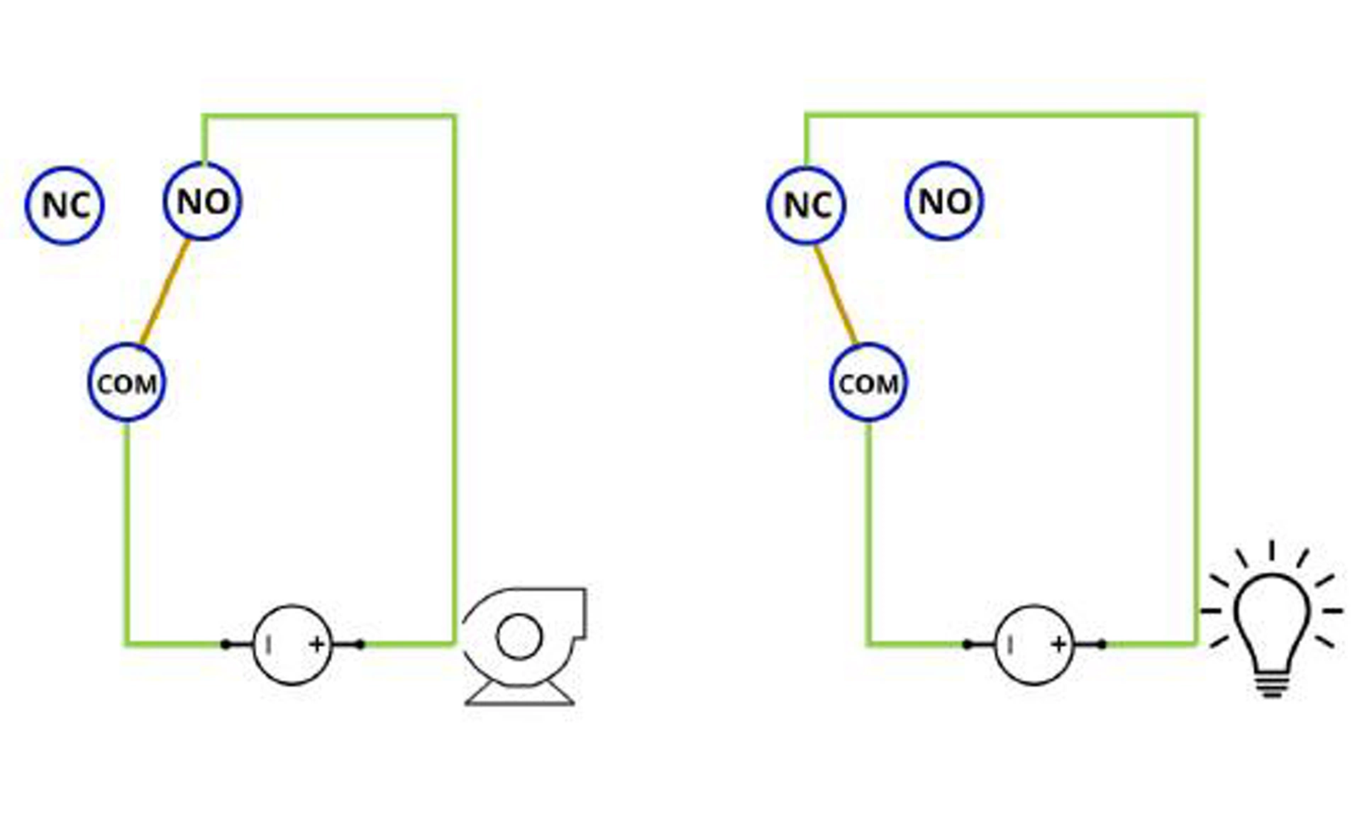
You can see how the loop will be open in a Fail state when wired to COM and NO, and the loop will be closed in a Fail state when wired to COM and NC.
Important
Because of this the COM and NO terminals are used when the relay is being used as a control device if the circuit should be switched Off in the event of a switch failure.
5.4 Relay power
The relay switches must be powered by a separate supply from the transmitter power.
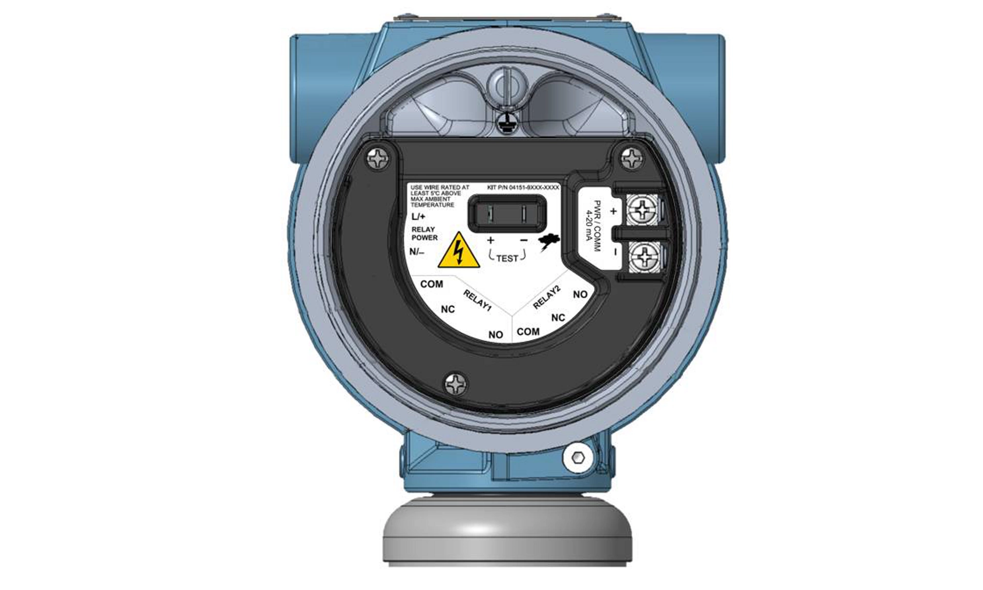
As shown in Figure 5-3, there are separate dedicated terminals for the relay power. The power supplied to the relays must be able to sufficiently drive the electromechanical relay coils of both switches to activate them. If using DC power, the terminals are polarity sensitive. If using AC power, there is no polarity sensitivity.
- Transmitter power is 11.5 to 42.4 Vdc.
- Relay power voltage is 21.5 to 60 Vdc or 20 to 264 Vac, 50.60 Hz.
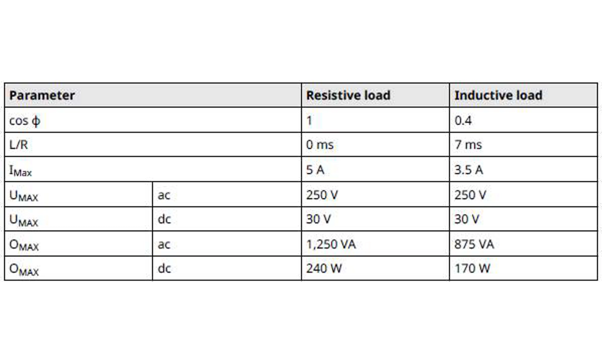
- Relay power current is 5 A maximum resistive load, 3.5 A maximum inductive load.
Table 5-1 shows the Relay 1 and Relay 2 load power requirements.
Table 5-1: Relay Power
warning
A double pole, single throw (DPST) On/Off switch must be fitted for safe disconnection of the power supply. Fit the DPST switch as near as possible to the pressure relay switch. Keep the DPST switch free of obstructions. Label the DPST switch to indicate it is the supply disconnection device for the power relay switch.
Figure 5-3: Relay Switches
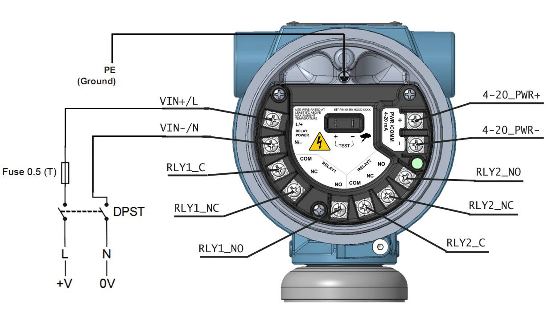
5.5 Relay configuration
When wiring AC power to RLYPWR terminals, include a fuse and optional double pole, single throw (DPST) switch.
The external DPST switch shown in Figure 5-3 is an optional local disconnect (customer supplied).
To view relay configuration, go to Diagnostics → Alerts → Relay/Process Alert 1 or Relay/Process Alert 2 → Configure Process Alert.
Procedure
1. Select the Configure Process Alert method in the transmitter device driver (DD).
2. Select either Relay and HART Status Alert or Relay and Analog Output Alarm for the Notification Mode in device setup.
The DD will go through the relay setup.
3. Select which variable you want the Process Alert to monitor along with the alert value and whether the status is Above High Side, Inside Window, Outside Window, or Below Low Side.
Depending on the selected option, set the high and low alert values. If you select Inside Window or Outside Window, you need to set both high and low alert values.
4. Select Position During Alert.
This is the switch's position during an active alert. This tells the software if the switch should be energized (between Common (COM) and Normally Open (NO) or de-energized (between COM and Normally Closed (NC) when in alert. Setting the switch's position will determine if the circuit is open or closed during an alert, but this also depends on how the connection to the relay is wired. For example, if the relay is wired to COM and NO, then when the transmitter switches, the relay will close the loop and power the device you are controlling with the relay.
5. Set up either a Deadband or Time Delay.
- The Deadband refers to specifying the region from the alert value where no action will occur. For example, if you set the HART Alert to 100 inH2O and the Deadband is 20 inH2O, the alert will be triggered at 100 inH2O, but the transmitter will not go back to operating conditions until it reaches 80 inH2O.
- The Time Delay is the amount of time the alert must be active before the device will report the alert.
6. In addition to configuring Process Alerts, you can also set up the relay to show its status on the transmitter display. To configure the transmitter display, go to Device Settings → Display. Then select which relay you want to show in the secondary area.
note
If using two switches as the same time, the physical switching will not be simultaneous in the event that the process alerts signal both switches to activate at the same time.
5.6 Commissioning a transmitter with relay switches
It is important to consider the sequence of configuring, wiring, and powering both the transmitter and relays when actively using relay switches.
Depending on the relay configuration and wiring, the relay-controlled equipment could receive power, or the transmitter could give early alerts or warnings. To avoid early alerts or warnings, it is important to power the transmitter after powering the relays. In addition, powering both the transmitter and relays prior to configuring the relays will avoid unnecessary trips.
Related information
Diagnostic messages
5.7 Relay switch operation examples
Table 5-2 describes the desired state of the loop between the relay and the device that is being controlled.
For example, if the controlled device should be On in a Fail state, Off in an Operational state, and On in an Alert state, the first row in Table 5-2 would be used.
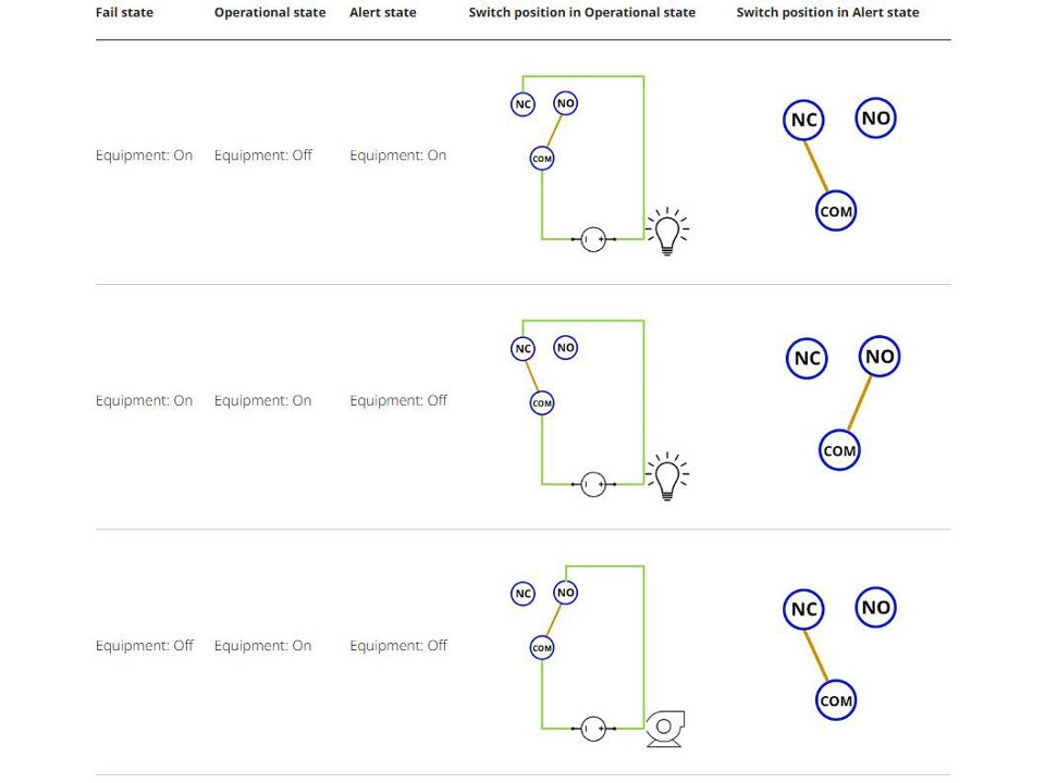
Table 5-2: Relay Switch Operation Examples
5.8 Relay tests
See Relay maintenance and operation (with output protocol code S) to learn more about relay tests and proof tests.
5.9 Relay diagnostics
See Diagnostic messages for more details about relay diagnostic and recommended troubleshooting actions.
6. Operation and maintenance
6.1 Overview
note
Calibration
If any trim is done improperly or with inaccurate equipment, it may degrade the transmitter's performance.
Emerson calibrates absolute pressure transmitters at the factory.
Trimming adjusts the position of the factory characterization curve.
Emerson provides instructions to perform configuration functions with the following:
- Communication device, such as AMS Trex
- AMS Device Manager
- AMS Device Configurator Bluetooth® app
- Quick Service buttons
6.2 Recommended calibration tasks
Procedure
1. Perform sensor zero/lower trim to compensate for mounting pressure effects. Refer to Manifold operation for instructions on properly draining and venting valves.
2. Set/check basic configuration parameters:
- Damping Value
- Output Type
- Output Units
- Range Points
6.3 Calibration overview
Note
Emerson fully calibrates the transmitter at the factory. Emerson provides a field calibration option to meet plant requirements or industry standards.
Note
Sensor calibration allows you to adjust the pressure (digital value) reported by the transmitter to be equal to a pressure standard. The sensor calibration can adjust the pressure offset to correct for mounting conditions or line pressure effects. Emerson recommends this correction.
Also, to calibrate the pressure range (pressure span or gain correction), you need accurate pressure standards (sources) to provide full calibration.
There are two parts to complete calibration of the transmitter: sensor calibration and analog output calibration.
Calibrating sensor
To perform a sensor trim or digital zero trim, see Trimming pressure signal.
Calibrating 4-20 mA output
With bench calibrations, you can calibrate the device for its desired operation range.
Straightforward connections to pressure source allow for a full calibration at the planned operating points. Exercise the transmitter over the desired pressure range to verify the analog output.
note
It is possible to degrade the performance of the transmitter if a trim is done improperly or with inaccurate equipment.
You can set the transmitter back to factory settings using the Recall Factory Trim command.
For transmitters that are field installed, manifolds allow the differential transmitter to be zeroed using the zero trim function. This field calibration will eliminate any pressure offsets caused by mounting effects (head effect of the oil fill) and static pressure effects of the process.
To determine the necessary trims:
Procedure
1. Apply pressure.
2. Check digital pressure; if the digital pressure does not match the applied pressure, perform a digital trim.
3. Check reported analog output against the live analog output. If they do not match, perform an analog output trim.
6.4 Trimming pressure signal
A sensor trim corrects the pressure offset and pressure range to match a pressure standard.
The upper sensor trim corrects the pressure range, and the lower sensor trim (zero trim) corrects the pressure offset. An accurate pressure standard is required for full calibration. You can perform a zero trim if the process is vented or the high and low side pressure are equal (for differential pressure transmitters).
Zero trim is a single-point offset adjustment. It is useful for compensating for mounting position effects and is most effective when performed with the transmitter installed in its final mounting position. As this correction maintains the slope of the characterization curve, do not use it in place of a sensor trim over the full sensor range.
When performing a zero trim, ensure that the equalizing valve is open and all wet legs are filled to the correct levels. Apply line pressure to the transmitter during a zero trim to eliminate line pressure errors.
Note
Do not perform a zero trim on an absolute pressure transmitter. Zero trim is zero based, and absolute pressure transmitters reference absolute zero. To correct mounting position effects on an absolute pressure transmitter, perform a lower sensor trim within the sensor trim function. The lower sensor trim function provides an offset correction similar to the zero trim function, but it does not require zero-based input.
Upper and lower sensor trim is a two-point sensor calibration where two end-point pressures are applied and all output is linearized between them; this calibration also requires an accurate pressure source. Always adjust the low trim value first to establish the correct offset. Adjustment of the high trim value provides a slope correction to the characterization curve based on the low trim value. The trim values help optimize performance over a specific measurement range.
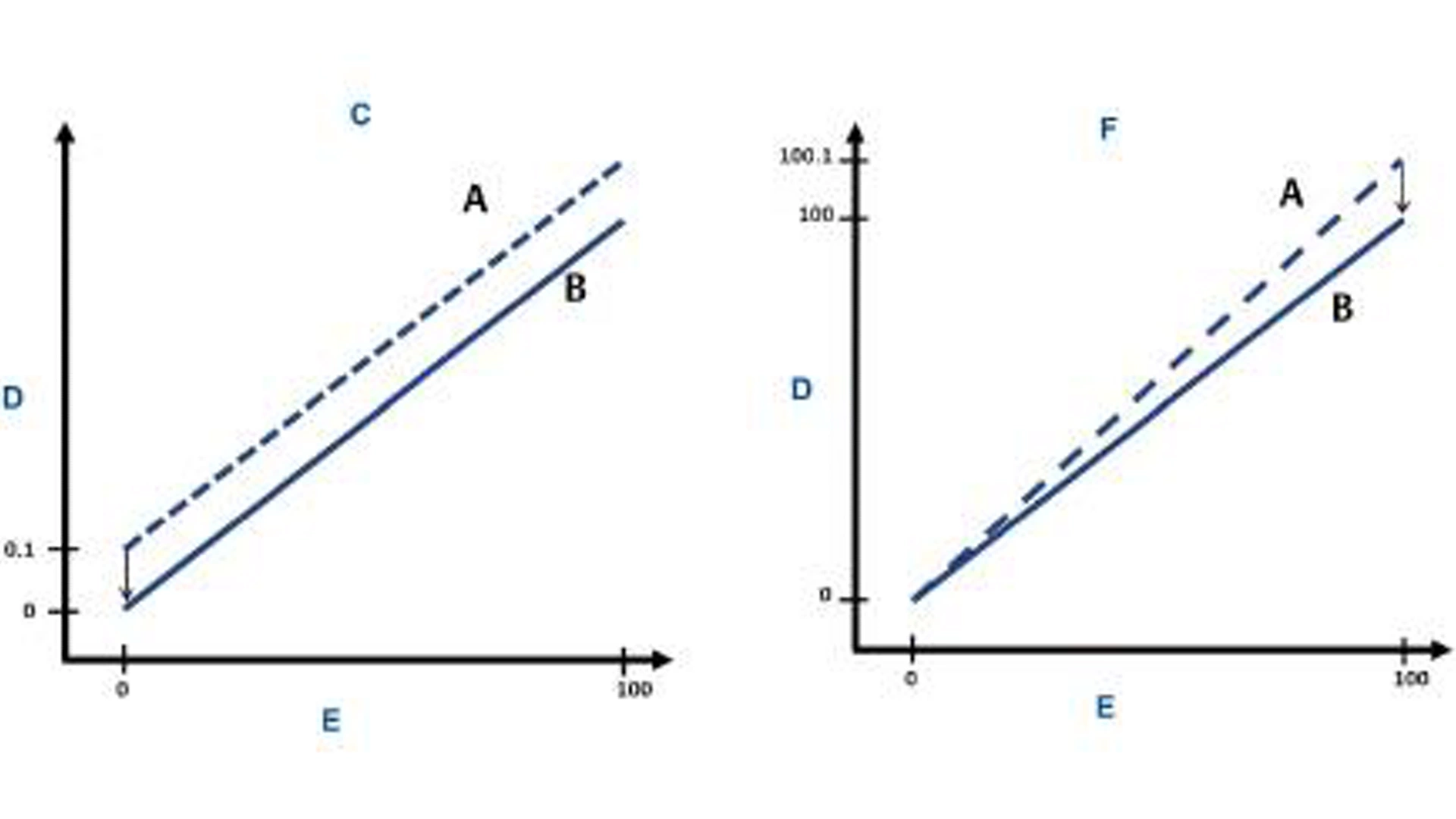
Figure 6-1: Sensor Trim Example
A. Before trim
B. After trim
C. Zero/lower sensor trim
D. Pressure reading
E. Pressure input
F. Upper sensor trim
6.5 Trimming the analog output
You can use the analog output trim command to adjust the transmitter's current output at the 4 and 20 mA points to match the plant standards.
Figure 6-2 and Figure 6-3 graphically show the two ways the characterization curve is affected when an analog output trim is performed.
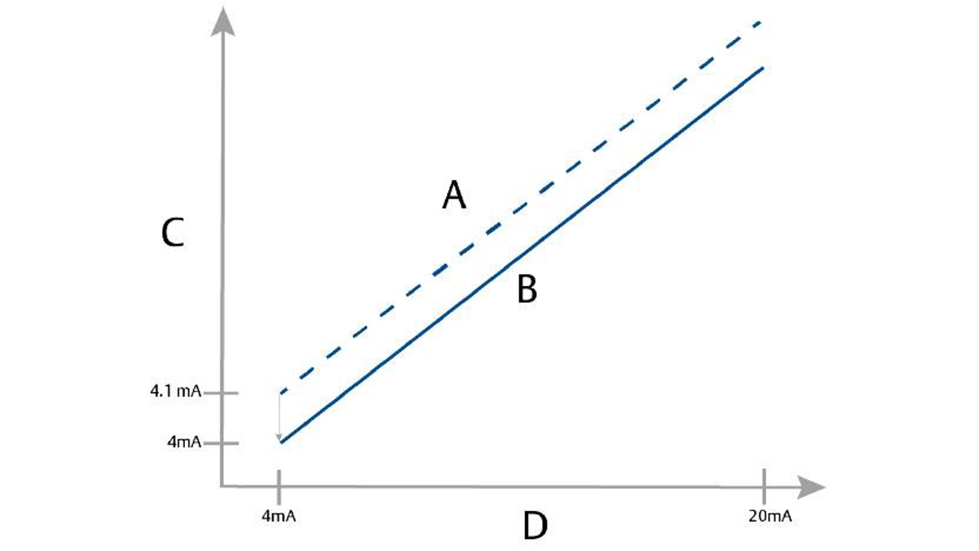
Figure 6-2: 4-20 mA Output Trim - Zero/Lower Trim
A. Before trim
B. After trim
C. Pressure reading
D. mA output
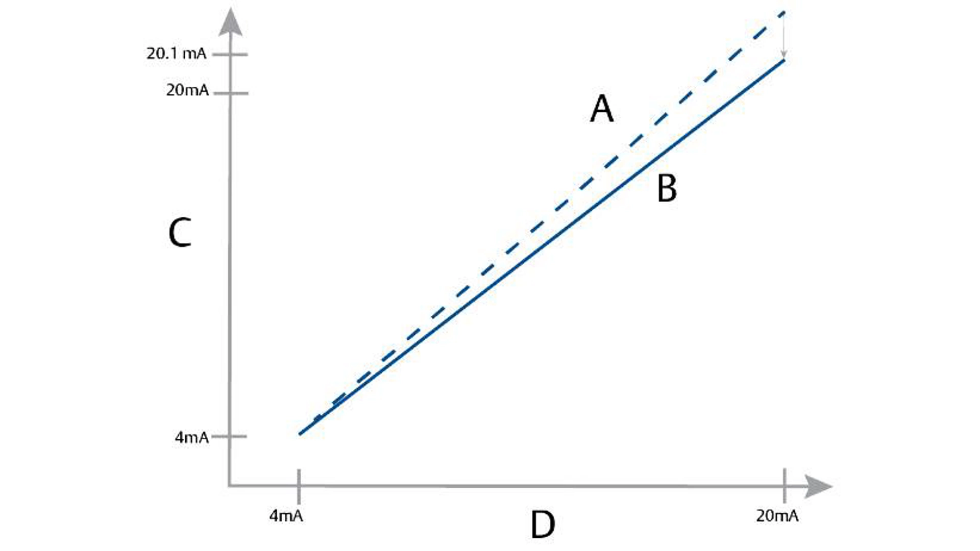
Figure 6-3: 4-20 mA Output Trim - Upper Trim
A. Before trim
B. After trim
C. Pressure reading
D. mA output
note
If you add a resistor to the loop, ensure that the power supply is sufficient to power the transmitter to a 20 mA output, or Alarm state if using High Alarm, with additional loop resistance.
Related information
Power supply for a 4–20 mA HART communication device
Perform a 4-20 mA output trim using a communication device
Procedure
Go to Device Settings → Calibration → Analog Output → Calibration → Analog Calibration.
6.6 Relay maintenance and operation (with output protocol code S)
The relay test feature built in the transmitter allows you to test different states of the relay and ensure that the configured operation is working as intended for the specific application.
To find the relay test feature, navigate to the Simulation section of the user interface and select Relay Test.
7. Troubleshooting
7.1 Troubleshooting overview
This chapter provides summarized troubleshooting suggestions for the most common operating problems.
7.2 Diagnostic messages
The following sections contain possible messages that appear on either the display, a communication device, or an AMS system. Use them to diagnose status messages.
- Failure (Diagnostic message: Failure)
- Function Check (Diagnostic message: Functional Check)
- Maintenance Required (Diagnostic message: Maintenance required)
- Out of Specification (Diagnostic message: Out of Specification)
Displayed status via HART® or Bluetooth® in Software Tools.
Sensor Module Failure | A failure has been detected in the sensor module. |
| Enabled | Factory | mA Alarm |
Electronics Board Failure | A failure has been detected in the electronic circuit board. | Replace the electronic circuit board. | Enabled | Factory | mA Alarm |
Incompatible Sensor Module | The electronic circuit board has detected a sensor module that is incompatible with the system. | Replace the incompatible sensor module. | Enabled | Factory | mA Alarm |
Incompatible Terminal Block | The electronic circuit board has detected a terminal block that is incompatible with the system. | Replace the incompatible terminal block. | Enabled | Factory | mA Alarm |
Relay Terminal Block Not Installed | Process Alerts have been configured to use relays, but the electronic circuit board was unable to detect a terminal block with relays. |
| Enabled | Factory | mA Alarm |
Terminal Block Failure | A failure has been detected in the terminal block. |
| Enabled | Factory | HART |
Incompatible Hardware | The electronic circuit board has detected incompatible hardware components with the device's software version. | Remove the incompatible hardware component(s) connected to the device. | Enabled | Factory | HART |
Sensor Communication Failure | The electronic circuit board has lost communication with the sensor module. |
| Enabled | Factory | mA Alarm |
7.3 Disassembling the transmitter
Disassembly of the transmitter may void hazardous location requirements.
warning
Explosion
Explosions could result in death or serious injury.
Do not remove the instrument cover in explosive atmospheres when the circuit is live.
warning
Follow all plant safety rules and procedures.
Procedure
1. Power down device.
2. Isolate and vent the process from the transmitter before removing the transmitter from service.
3. Remove all electrical leads and disconnect conduit.
4. Remove the transmitter from the process connection.
- The Rosemount 4051S Coplanar™ Transmitter is attached to the process connection by four bolts and two cap screws.
Remove the bolts and screws and separate the transmitter from the process connection. Leave the process connection in place and ready for reinstallation. - The 4051S In-Line Transmitter is attached to the process by a single hex nut process connection.
Loosen the hex nut to separate the transmitter from the process. Do not wrench on neck of transmitter.
5. Clean isolating diaphragms with a soft rag and a mild cleaning solution, and rinse with clear water.
note
Do not scratch, puncture, or depress the isolating diaphragms.
6. Whenever you remove the process flange or flange adapters, visually inspect the PTFE O-rings. Replace the O-rings if they show any signs of damage, such as nicks or cuts.
Note
You may reuse undamaged O-rings.
Related information
Inline gauge transmitter orientation
7.4 Reassembly procedures
Note
The V-seal must be installed at the bottom of the housing.
Procedure
1. Apply a light coat of low temperature silicon grease to the sensor module threads and O-ring.
2. Thread the housing completely onto the sensor module.
warning
The housing must be no more than one full turn from flush with the sensor module to comply with explosion-proof requirements.
3. Tighten the housing rotation set screw using a 3/32-inch hex wrench.
Carbon steel (CS)-ASTM-A449 Standard | 300 in-lb (34 N-m) | 650 in-lb (73 N-m) |
316 stainless steel (SST)—Option L4 | 150 in-lb (17 N-m) | 300 in-lb (34 N-m) |
ASTM-A-193-B7M—Option L5 | 300 in-lb (34 N-m) | 650 in-lb (73 N-m) |
Alloy K-500 —Option L6 | 300 in-lb (34 N-m) | 650 in-lb (73 N-m) |
ASTM-A-453-660—Option L7 | 150 in-lb (17 N-m) | 300 in-lb (34 N-m) |
ASTM-A-193-B8M—Option L8 | 150 in-lb (17 N-m) | 300 in-lb (34 N-m) |
6. If you replaced the PTFE sensor module O-rings, re-torque the flange bolts after installation to compensate for cold flow.
7. Install the drain/vent valve:
a) Apply sealing tape to the threads on the seat. Starting at the base of the valve with the threaded end pointing toward the installer, apply two clockwise turns of sealing tape.
b) Take care to place the opening on the valve so that process fluid will drain toward the ground and away from human contact when the valve is opened.
c) Tighten the drain/vent valve to 250 in-lb (28.25 N-m).
Postrequisites
After replacing O-rings on Range 1 Transmitters and re-installing the process flange, expose the transmitter to a temperature of 185 °F (85 °C) for two hours. Then re-tighten the flange bolts in a cross pattern, and again expose the transmitter to a temperature of 185 °F (85 °C) for two hours before calibration.
8. Safety Instrumented Systems (SIS)
The safety-critical output of the Rosemount 4051S pressure Transmitter is provided through a two-wire, 4–20 mA signal representing pressure. The 4051S safety-certified pressure transmitter is certified to:
- Low and high demand: Type B element
- Route 2H, low demand application: Safety Integrity Level (SIL) 2 for random integrity at HFT=0, SIL3 for random integrity at HFT=1
- Route 2H, high demand application: SIL2 and SIL3 for random integrity at HFT=1
- Route 1H where the SFF ≥ 90 percent: SIL2 for random integrity at HFT=0, SIL3 for random integrity at HFT=1
- SIL3 for systematic integrity
8.1 Rosemount 4051S safety certified identification
All 4051S transmitters must be identified as safety certified before installing into Safety Instrumented Systems (SIS).
Procedure
1. Check NAMUR Software Revision located on the metal device tag: SW_._._.
For more details on device revisions, refer to NAMUR NE53 Device Revision History at NAMUR NE-53 Documentation for Measurement Instruments.
2. Verify that the option code QT is included in the transmitter model code.
3. Devices used in safety applications with ambient temperatures below -40 °F (-40 °C) require option codes QT and BR5 or BR6.
8.2 Installation in Safety Instrumented Systems (SIS) applications
warning
Installations must be performed by qualified personnel.
No special installation is required in addition to the standard installation practices outlined in the applicable product manual.
warning
Always ensure a proper seal by installing the electronics housing cover(s) so that metal contacts metal if housing is used.
See the Specifications section of the Rosemount 4051S Pressure Transmitter Product Data Sheet for environmental and operational limits.
The loop should be designed so the terminal voltage does not drop below 11.5 Vdc for the Rosemount 4051S when the transmitter output is 23.0 mA.
Set the Security switch to ON to prevent accidental or deliberate change of configuration data during normal operation.
8.3 Configuring in Safety Instrumented Systems (SIS) applications
Use any HART®-capable configuration tool to communicate with and verify configuration of the transmitter.
warning
Transmitter output is not safety-rated during the following: configuration changes, multidrop, and loop test. Use alternative means to ensure process safety during transmitter configuration and maintenance activities.
8.4 Damping
User-selected damping will affect the transmitter's ability to respond to changes in the applied process. The damping value and response time must not exceed the loop requirements.
8.5 Alarm and saturation levels
Configure a distributed control system (DCS) or safety logic solver to match transmitter configuration.
The following three figures identify the various alarm levels available and their operations values.
Figure 8-1: Rosemount Alarm Level
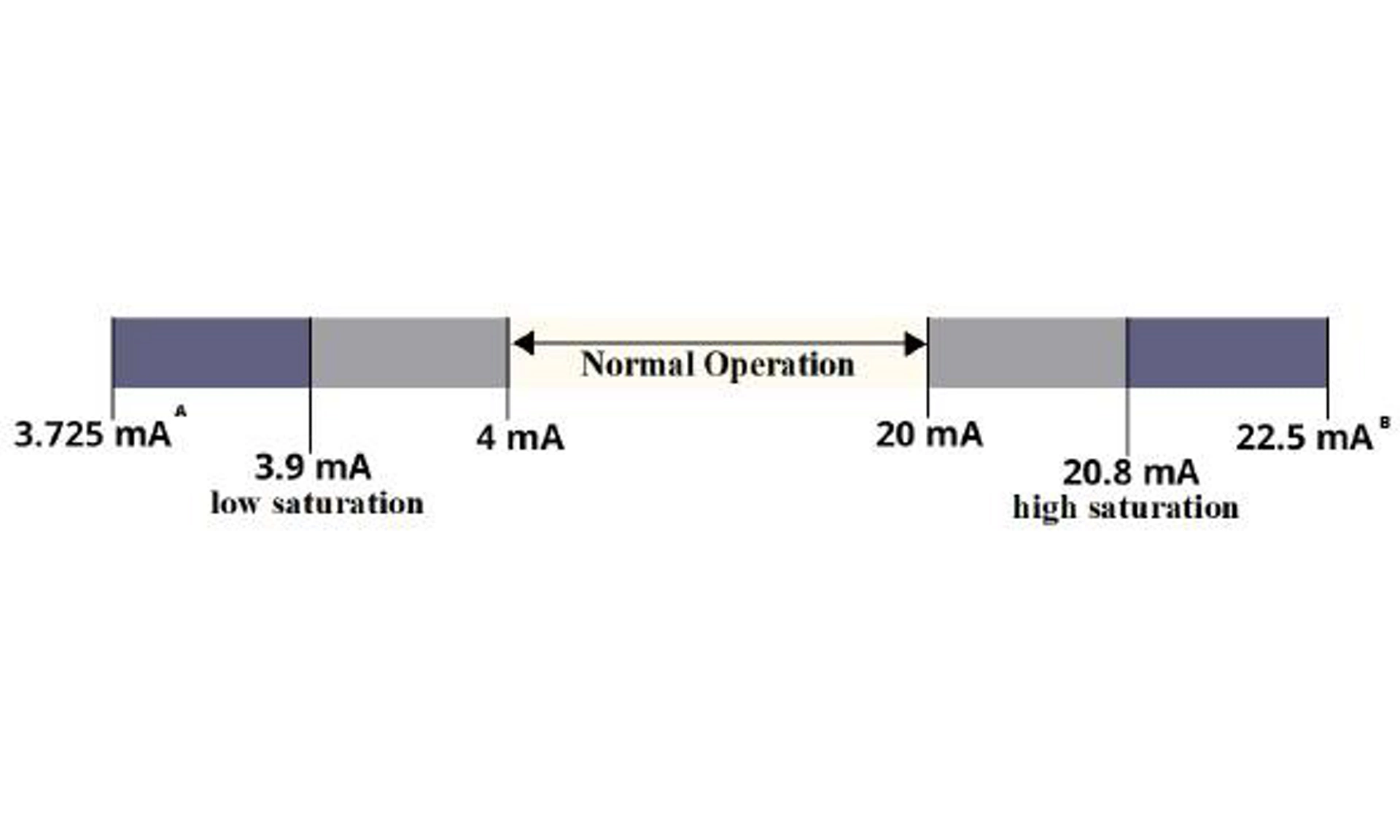
A. Transmitter failure, hardware or software alarm in Low position.
B. Transmitter failure, hardware or software alarm in High position.
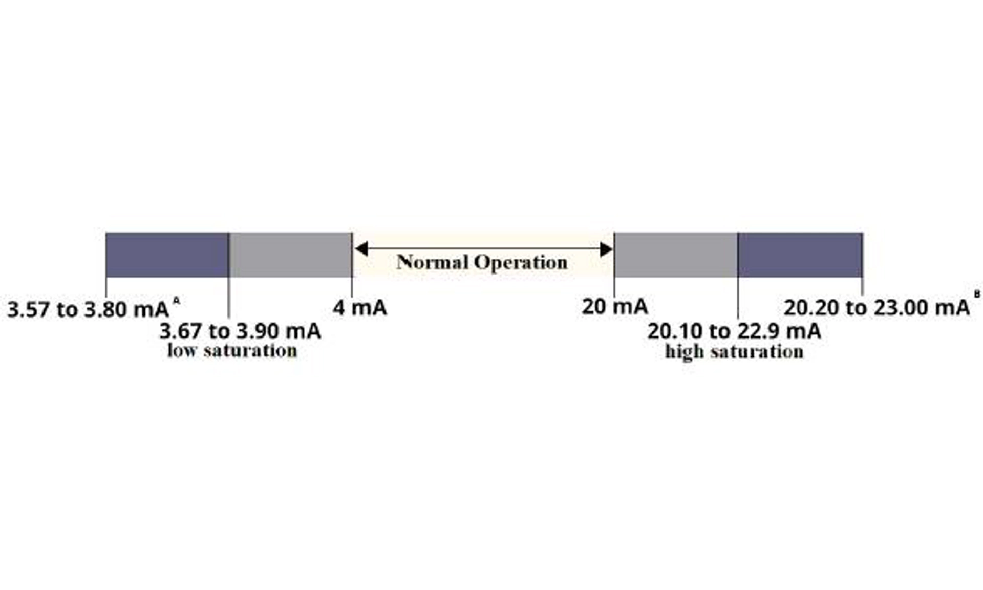
Figure 8-2: NAMUR Alarm Level
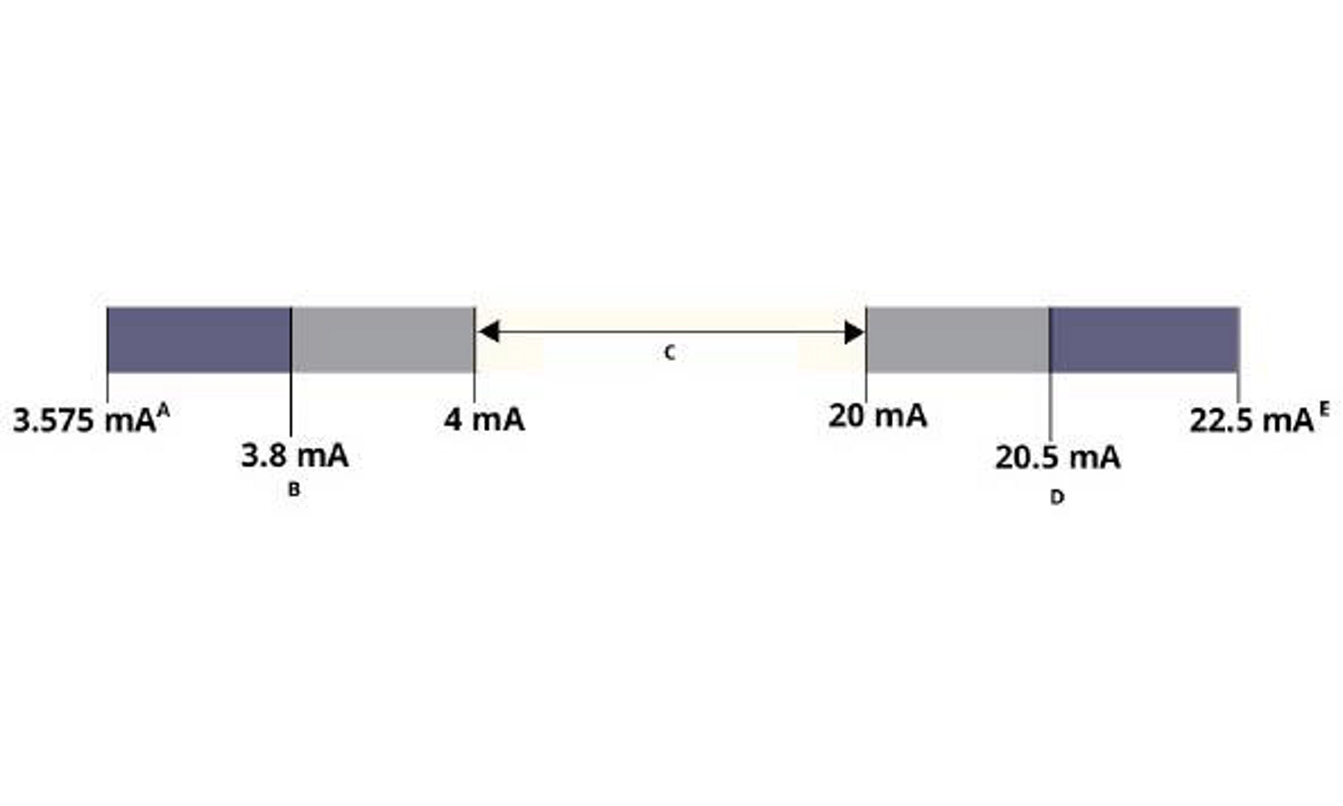
A. Transmitter failure, hardware or software alarm in Low position.
B. Low saturation
C. Normal operation
D. High saturation
E. Transmitter failure, hardware or software alarm in High position.
Figure 8-3: Custom Alarm Level
Low alarm must be at least 0.1 mA lower than the low saturation value.
A. Transmitter failure, hardware or software alarm in Low position.
B. Transmitter failure, hardware or software alarm in High position.
Setting the alarm values and direction varies depending on whether the Hardware Switch, included with option code S, is installed. You can use a HART® master or communicator to set the Alarm and Saturation values.
8.6 Safety Instrumented Systems (SIS) operation and maintenance
Emerson recommends the following proof tests. In the event that an error is found in the safety and functionality, proof test results and corrective actions taken can be documented at Contact Measurement Instrumentation Solutions Customer Service.
warning
All proof test procedures must be carried out by qualified personnel.
Use a communication device to perform a loop test, analog output trim, or sensor trim. Security switch should be in the unlocked position during proof test execution and repositioned in the locked position after execution.

How to Perform Proof Tests on the Rosemount 4051S Pressure Transmitter | Emerson
8.7 Inspection
The Rosemount 4051S is repairable by major component replacement.
All failures detected by the transmitter diagnostics or by the proof-test must be reported.
warning
All product repair and part replacement must be performed by qualified personnel.
A. Reference data
A.1 Ordering information, specifications, and drawings
To view current Rosemount 4051S ordering information, specifications, and drawings, follow these steps:
Procedure
1. Go to Emerson.com and search for "Rosemount 4051S".
2. Scroll as needed to the green menu bar and click Documents & Drawings.
3. For installation drawings, click Drawings & Schematics and select the appropriate document.
4. For ordering information, specifications, and dimensional drawings, click Data Sheets & Bulletins and select the appropriate Product Data Sheet.
5. For the Declaration of Conformity, click Certificates & Approvals and select the most current document.
A.2 Product Certifications
To view current Rosemount 4051S product certifications, click Documents & Drawings and see the Rosemount 4051S Pressure Transmitter Quick Start Guide.
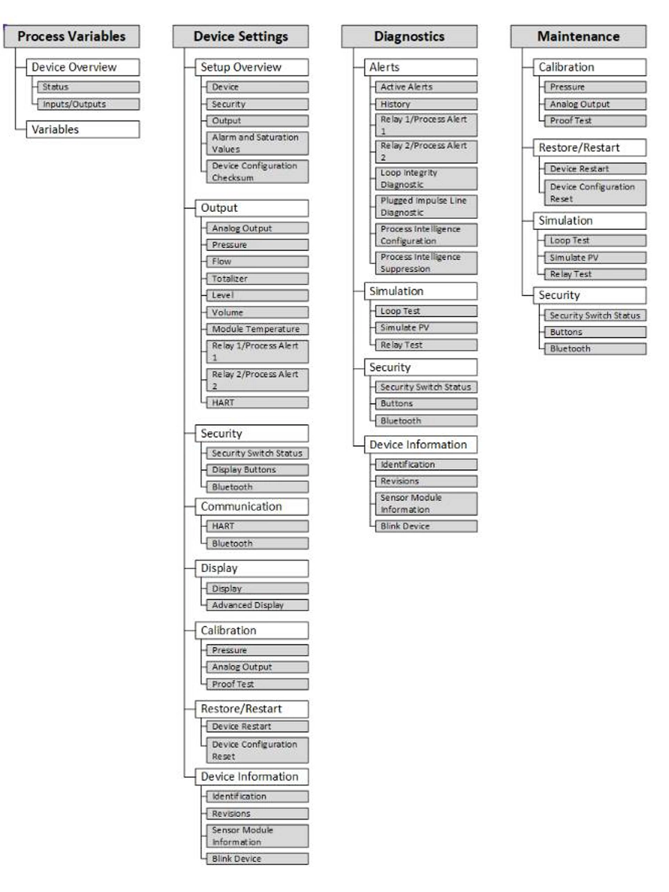
Figure B-1: Menu Trees Overview
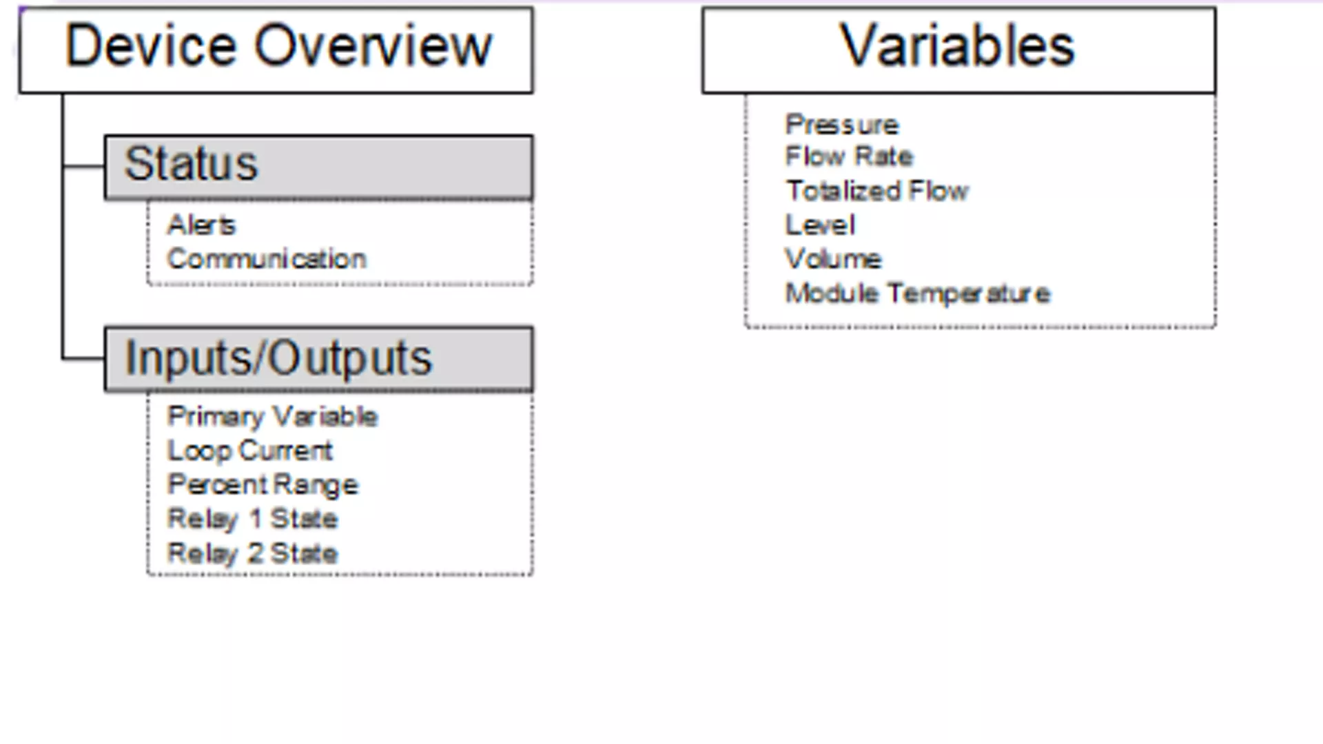
Figure B-2: Process Variables menu
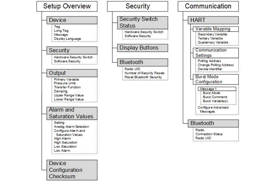
Figure B-3: Device Settings 1
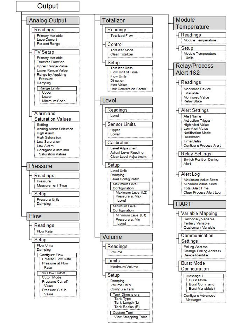
Figure B-4: Device Settings 2
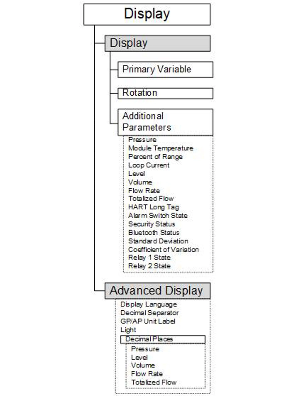
Figure B-5: Device Settings 3
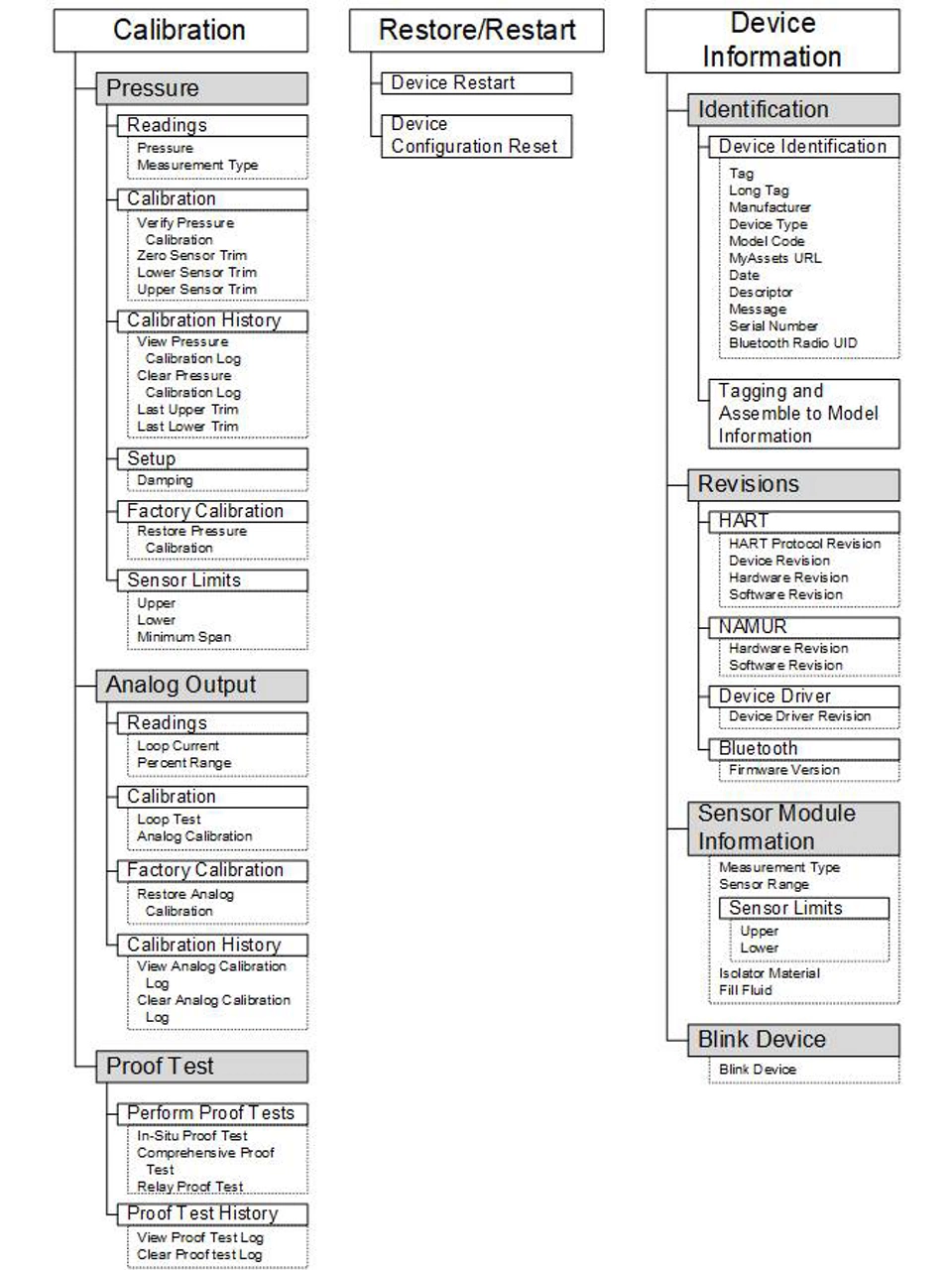
Figure B-6: Device Settings 4
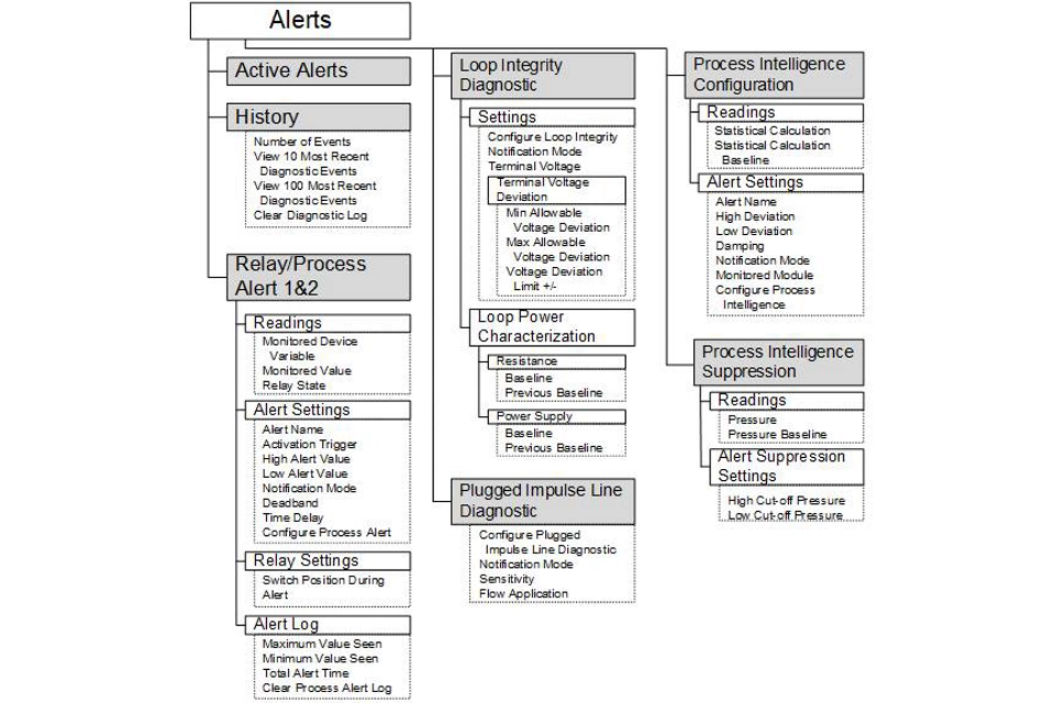
Figure B-7: Diagnostics 1
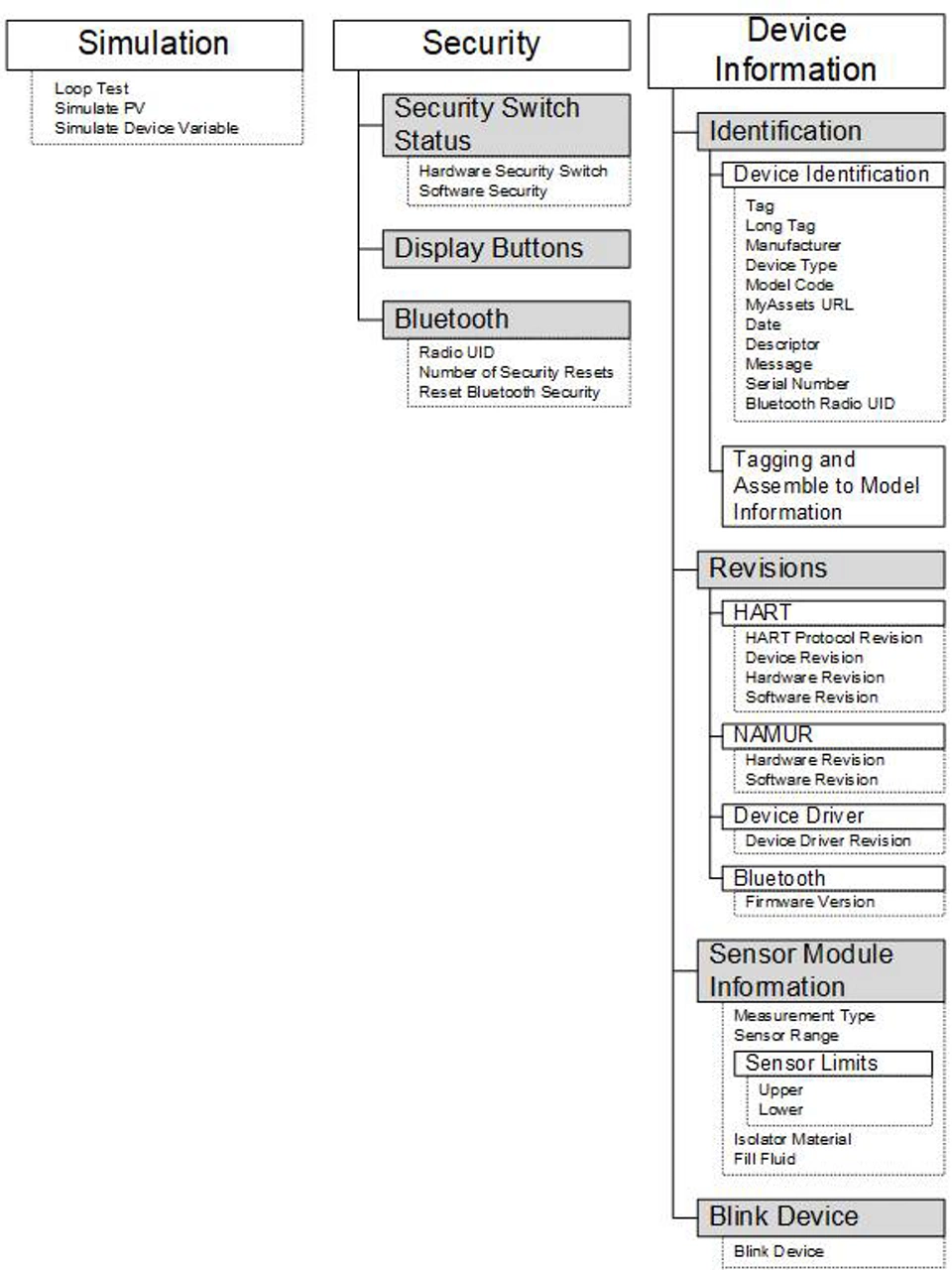
Figure B-8: Diagnostics 2
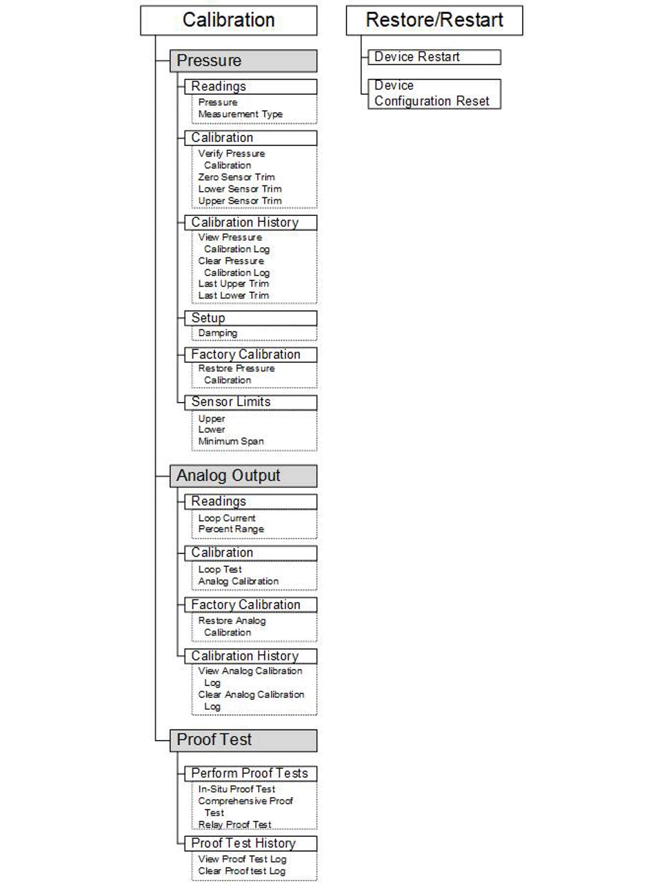
Figure B-9: Maintenance 1
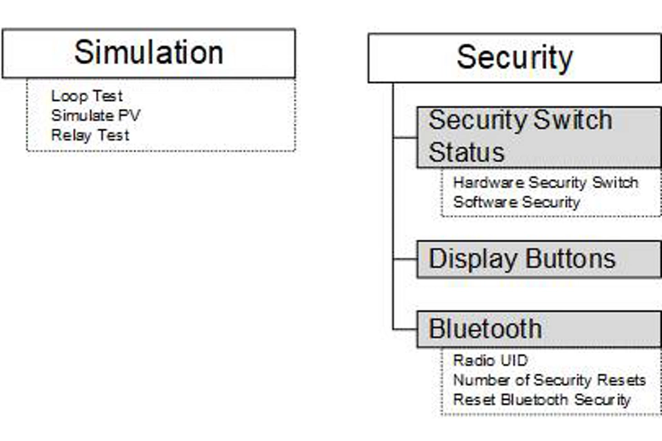
Figure B-10: Maintenance 2
C. Quick Service buttons