

Introduction
1. Installation
- 1.1 Installation Considerations
- 1.2 Verify and Set the Switches
- 1.3 Installation
- 1.4 Wiring
- 1.5 Load Limitations
- 1.6 Grounding
2. Standard Configuration
- 2.1 Configuration Overview
- 2.2 Configuration
- 2.3 Device output configuration
- 2.4 LCD display information
- 2.5 Device information
- 2.6 Loop Test
- 2.7 Device Restart and Device Configuration Reset
3. Diagnostics Configuration
- 3.1 Diagnostics Overview
- 3.2 RTD Measurement Protection
- 3.3 Thermocouple Degradation Diagnostic
- 3.4 Hot Backup
- 3.5 Sensor Drift Alert
- 3.6 Loop Integrity
- 3.7 Process Alerts
4. Operation & Maintenance
5. Troubleshooting
6. Rosemount X-well Technology
- 6.1 Wiring for Rosemount X-well Technology
- 6.2 Installation for Rosemount X-well Technology
- 6.3 Configure Rosemount X-well Technology
- 6.4 Calibrate Rosemount X-well Technology
- 6.5 X-well Technology Troubleshooting
7. Safety Instrumented Systems (SIS)
Introduction
Features and benefits
Improved ease of use
- With Bluetooth® connectivity, quickly configure, service, and troubleshoot at speeds up to 10 times faster than traditional HART® connections.
- Quick Service buttons provide straightforward menus and built-in configuration, allowing you to quickly commission the device.
- ReadyConnect™ technology allows for sensor configuration with the push of a button, automatically detecting the sensor type, number of wires, and Callendar-Van Dusen coefficients, to save you configuration and commissioning time while delivering the best accuracy.
Full diagnostic coverage from sensor to control room
- Identify issues before they impact operations or compromise safety with complete diagnostic coverage from your temperature sensor to your control room with sensor health diagnostics, dual input capabilities, and continuous electrical loop monitoring.
- The Loop Integrity diagnostic continuously monitors the electrical loop to detect issues that affect the communication signal and will alert you to corrosion, water in the housing, or an unstable power supply.
- RTD Measurement Protection seamlessly switches from a 4-wire to a 3-wire RTD sensor input configuration if one of the four sensor wires becomes broken, corroded, or loose anywhere from the sensorelement to the transmitter terminal connections. Your measurement will be maintained without process disruption, and a maintenance alert will be generated.
- Diagnostic logging capability stores up to 100 events, providing historical insight into device health.
- Improve visibility to your operations with the Process Alert capability that provides variable dynamic tracking within alarm limits.
Reset measurement expectations with Ultra Performance Class
- Control closer to your setpoint with 0.05 °C accuracy.
- Extend calibration intervals with 20-year stability.
- Have confidence in your measurement reliability with 20-year limited warranty.
- Ensure the most accurate dual sensor measurement with dual 4-wire input.
Eliminate thermowell challenges with Rosemount X-well™ Technology
- Non-intrusive solution provides accurate and reliable process temperature measurement in applications up to 1202 °F (650 °C).
- Remote mount capability provides installation flexibility.
- Single model configuration greatly reduces specification complexity.
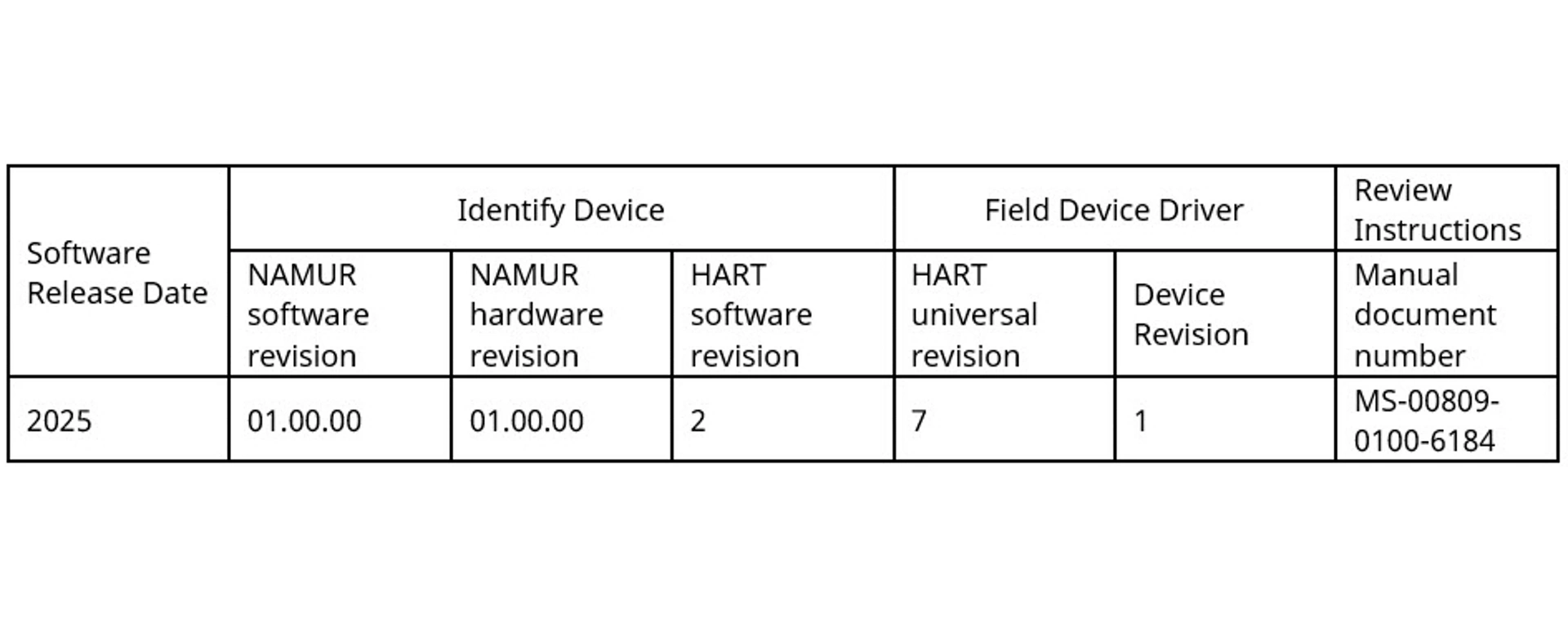
3144S Revisions
This table defines the NAMUR NE53 Hardware and Software Revisions for products assembled with the 3144S HART® feature board.
This Digital Manual is an abbreviated version of the complete Reference Manual which can be found by clicking on “View PDF” button at the top of the page. Please read the entire Reference Manual for all Cautions and Warnings prior to installation.
1. Installation
1.1 Installation Considerations
General
Electrical temperature sensors, such as RTDs and thermocouples (T/Cs), produce low-level signals proportional to temperature. The Rosemount 3144S Temperature Transmitter converts these low-level signals to digital information, then transmits the signals to the control system via two power/signal wires and HART®.
Only qualified personnel should install the transmitter. No special installation is required in addition to the standard installation practices outlined in this document. Always ensure a proper seal by installing the electronics housing covers so that metal contacts metal.
The transmitter accepts male conduit fittings with ½-14 NPT or M20 x 1.5 (CM20). You can use optional mounting brackets to mount the transmitter to a flat surface (using the L mounting bracket, option code B5 or BH) or a 2-inch (51 mm) diameter pipe (using the U mounting bracket, option code B4 or BE).
The transmitter may require supplementary support under high-vibration conditions, particularly if used with extensive thermowell lagging or long extension fittings. Emerson recommends using pipe-stand mounting with one of the optional mounting brackets in high-vibration conditions.
warning
Physical access
Unauthorized personnel may potentially cause significant damage to and/or misconfiguration of end users’ equipment. This could be intentional or unintentional and needs to be protected against.
Physical security is an important part of any security program and fundamental in protecting your system. Restrict physical access by unauthorized personnel to protect end users’ assets. This is true for all systems used within the facility.
Software compatibility
Verify that the latest device driver (DD) is loaded on your systems to ensure proper communications.
To download a new DD, visit Software & Drivers.
Temperature effects
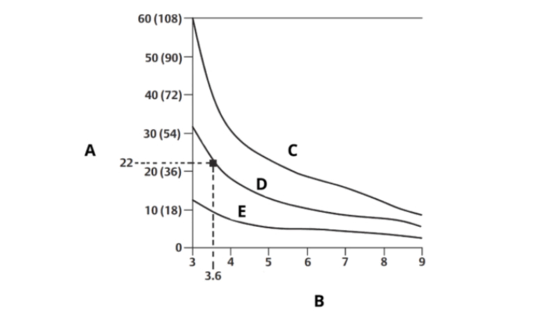
The transmitter will operate within specifications for ambient temperatures between -40 and +/-185°F (-40 and +/-85°C). Since heat from the process is transferred from the thermowell to the transmitter housing, if the expected process temperature is near or beyond specification limits, consider using additional thermowell lagging, an extension nipple, or a remote mounting configuration to isolate the transmitter from the process. The image on the right details the relationship between housing temperature rise and extension length.
A. Housing temperature rise above ambient: °C (°F)
B. Extension length (in.)
C. 1500 °F (815 °C) oven temperature
D. 1004 °F (540 °C) oven temperature
E. 482 °F (250 °C) oven temperature
Example
The maximum permissible housing temperature rise (T) can be calculated by subtracting the maximum ambient temperature (A) from the transmitter’s ambient temperature specification limit (S). For instance, if A = 40 °C.
T = S – A
T = 85 °C – 40 °C
T = 45 °C
For a process temperature of 1004 °F (+540 °C), an extension length of 3.6 in. (91 mm) yields a housing temperature rise (R) of 40 °F (22 °C), providing a safety margin of 41 °F (23 °C). A 6-inch (152 mm) extension length (R = 18 °F [10 °C]) offers a higher safety margin (63 °F [35 °C]) and reduces temperature-effect errors but would probably require extra transmitter support. Gauge the requirements for individual applications along this scale. If using a thermowell with lagging, you can reduce the extension length by the length of the lagging.
Humid or corrosive environments
The Rosemount 3144S Transmitter has a highly reliable dual compartment housing designed to resist moisture and corrosion. The sealed electronics module is mounted in a compartment that is isolated from the terminal side with conduit entries. O-ring seals protect the interior when the covers are properly installed. In humid environments, however, it is possible for moisture to accumulate in conduit lines and drain into the housing.
Location and position
When choosing an installation location and position, consider how you will access the transmitter.
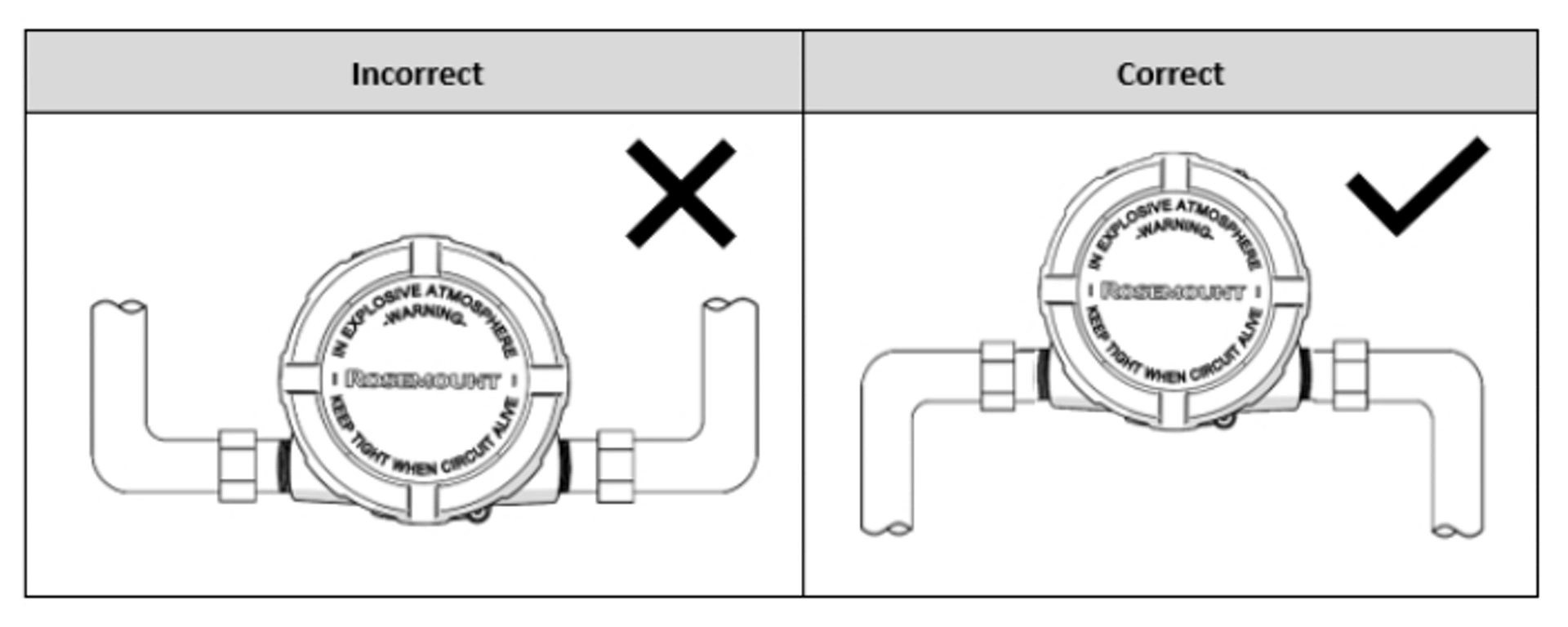
note
The terminal compartment could fill with water if the transmitter is mounted at a low point in the conduit run. If possible, mount the transmitter at a high point in the conduit run so moisture from the conduits will not drain into the housing.
Ensure that the transmitter mounting location allows you to access both the terminal and circuit side, providing adequate clearance for cover removal. Additional room is required for LCD display installation on the circuit side.
warning
Each transmitter is marked with a nameplate indicating the product certifications. Install the transmitter according to all applicable installation codes, and approval and installation drawings. Verify that the operating atmosphere of the transmitter is consistent with the hazardous location certifications. Once a device labeled with multiple approval types is installed, it may not be reinstalled using any of the other label protection types. To ensure this, permanently mark the nameplate to indicate the protection type used.
1.2 Verify and set the switches
Setting the loop to manual
Set the process application loop to manual when sending or requesting data that would disrupt the loop or change the output of the transmitter. The field communicator or AMS Device Manager will prompt to set the loop to manual, when necessary. Acknowledging the prompt does not set the loop to manual; it is only a reminder. Setting the loop to manual is a separate operation.
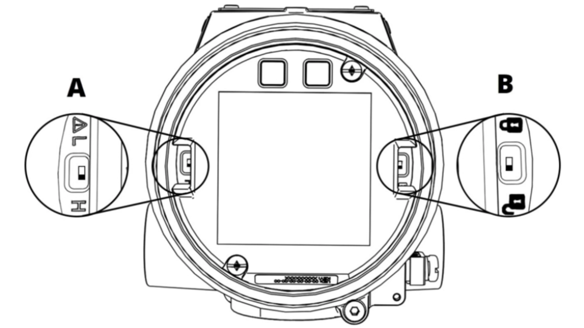
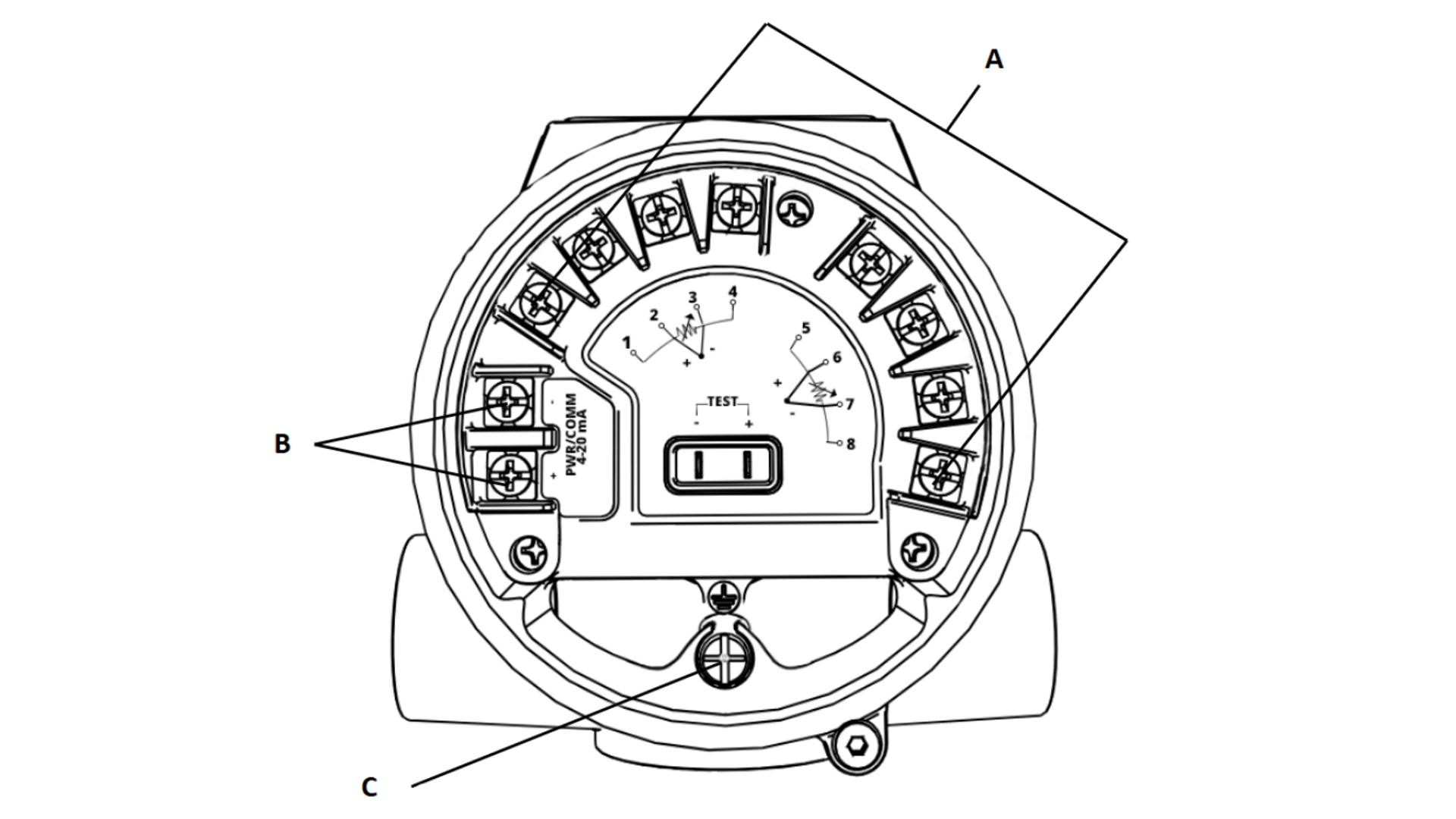
A. Alarm switch
B. Security switch
Security switch
The transmitter is equipped with a Write-Protect/Security switch that can be positioned to prevent accidental or deliberate change of configuration data. This switch is shown on the right in the image above.
Alarm switch
An automatic diagnostic routine monitors the transmitter during normal operation. If the diagnostic routine detects a sensor failure or an electronics failure, the transmitter goes into alarm (High or Low depending on the position of the Alarm switch). The analog alarm and saturation values used by the transmitter depend on whether it is configured to standard or NAMUR-compliant operation. These values are also custom-configurable in both the factory and the field using HART® communication. This switch is shown on the left in the image above. The limits are:
- 20.2 ≤ I ≤ 23.0 for high alarm
- 20.1 ≤ I ≤ 22.9 for high saturation
- 3.67 ≤ I ≤ 3.90 for low saturation
- 3.57 ≤ I ≤ 3.80 for low alarm
1.3 Installation
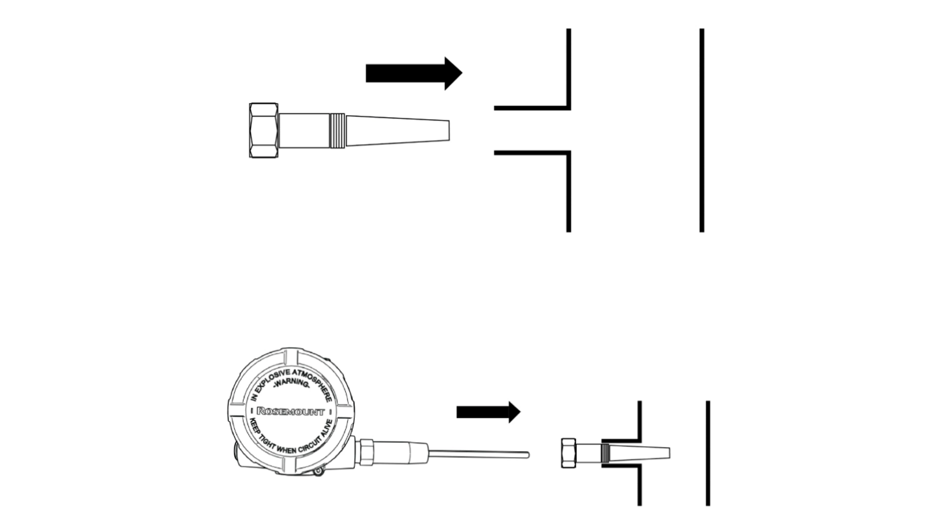
Procedure
1. Mount the thermowell to the process container wall.
2. Install and tighten thermowells.
3. Perform a leak check.
4. Attach any necessary unions, couplings, and extension fittings. Seal the fitting threads with an approved thread sealant, such as silicone or PTFE tape (if required).
5. Screw the sensor (and transmitter, if factory assembled) into the thermowell or directly into the process (depending on installation requirements).
6. Verify all sealing requirements.
7. Attach the transmitter to the thermowell/sensor assembly (if not factory assembled). Seal all threads with an approved thread sealant, such as silicone or PTFE tape (if required).
8. Install field wiring conduit into the open transmitter conduit entry and feed wires into the transmitter housing.
9. Pull the field wiring leads into the terminal side of the housing.
10. Attach the sensor leads to the transmitter sensor terminals. The wiring diagram is located on the terminal block. See Section 1.4 for wiring instructions.
1.4 Wiring
warning
Do not run unshielded signal wiring in conduit or open trays with power wiring or near heavy electrical equipment because high voltage may be present on the leads and may cause an electrical shock.
note
Do not apply high voltage (e.g., AC line voltage) to the power or sensor terminals. The high voltage can damage the unit.
Field Wiring
An external power supply is required to operate the transmitter. The power to the transmitter is supplied over the signal wiring. Signal wiring does not need to be shielded, but twisted pairs should be used for best results.
Procedure
1. Remove the transmitter covers. Do not remove the transmitter covers in an explosive atmosphere when the circuit is live.
2. Connect the positive power lead to the terminal marked “+” and the negative power lead to the terminal marked “–” as shown in image on the right. Crimped lugs are recommended when wiring to screw terminals.
3. Tighten the terminal screws to ensure good contact is made.
4. Replace the transmitter covers making sure both transmitter covers are fully engaged to meet explosion-proof requirements.
A. Sensor terminals (1-8)
B. Power terminals
C. Ground
Power/current loop connections
Use copper wire of a sufficient size to ensure that the voltage across the transmitter power terminals does not go below 11.5 Vdc for Classic Performance and 16.7 Vdc for Ultra Performance.
1. Connect the current signal leads as shown in the image above.
2. Recheck the polarity and connections.
3. Turn the power ON.
note
Do not connect the power/signal wiring to the test clips. The voltage present on the power/signal leads may permanently damage the reverse-polarity protection diode built into the test clips.
note
The signal wire may be grounded at any point or left ungrounded.
note
AMS Device Manager software or a Field Communicator can be connected at any termination point in the signal loop. The signal loop must have between 250 and 1100 ohms load for communications.
Wiring diagrams are located on the terminal block. Terminals 1-4 correspond to Measurement 1, and Terminals 5-8 correspond to Measurement 2. See Section 6.1 for X-well wiring information.
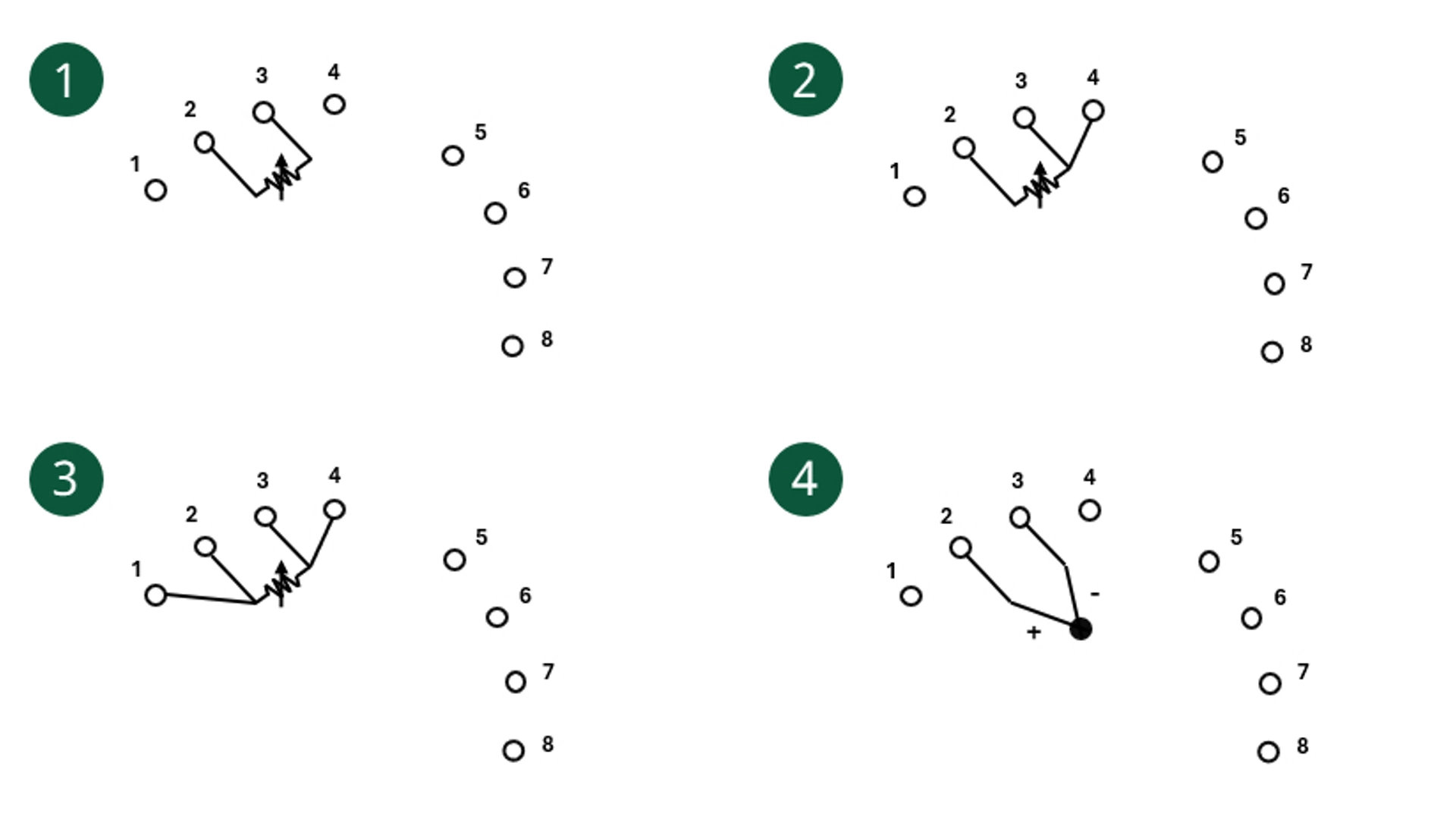
1. 2-wire RTD & ohms
2. 3-wire RTD & ohms
3. 4-wire RTD & ohms
4. Thermocouples & mV
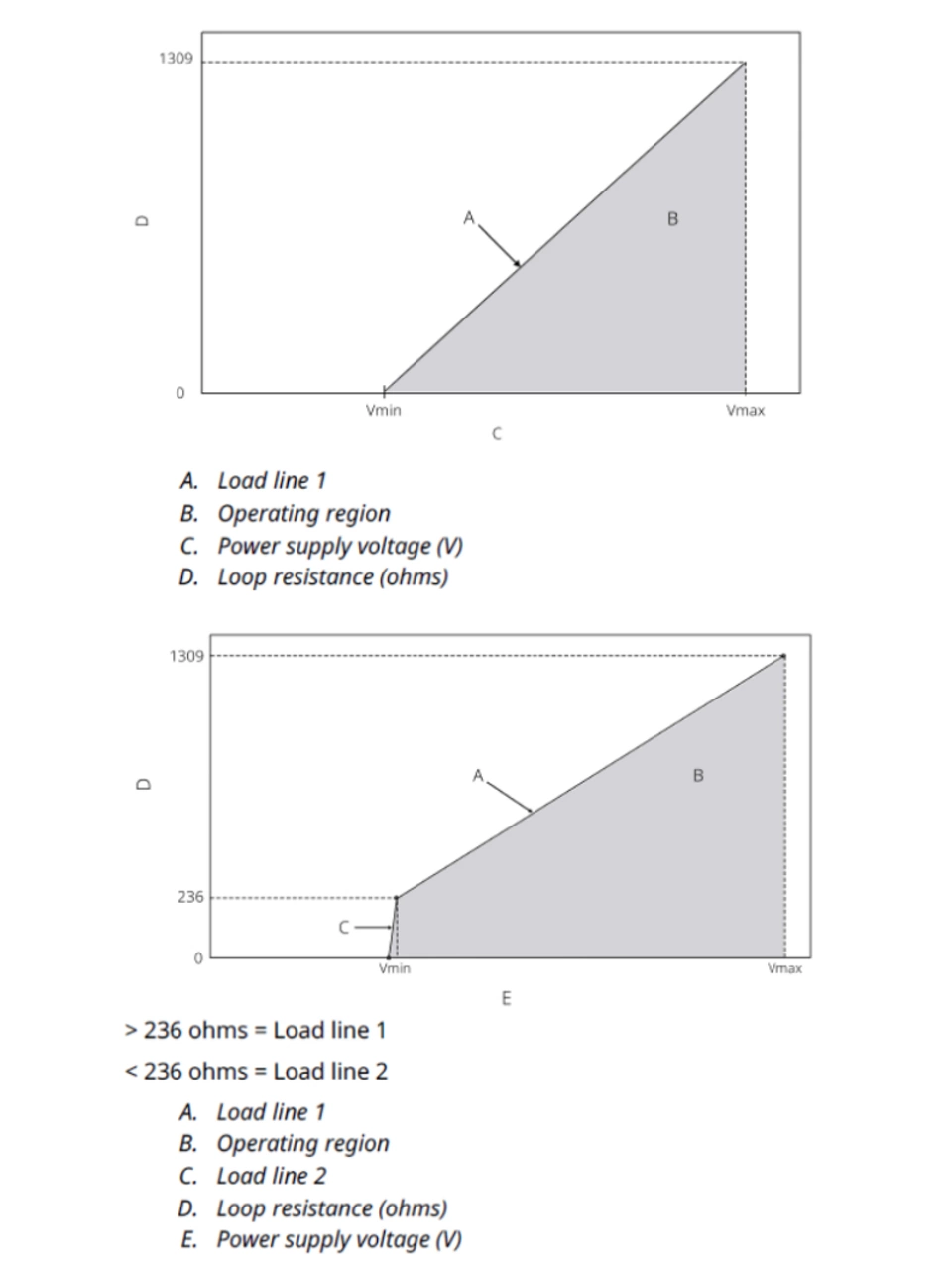
1.5 Load Limitations
The voltage required across the transmitter power terminals is dependent on loop resistance and product performance class (as listed in the model code).
The voltage input range is 11.5 to 42.4 Vdc for Classic Performance (see the top graph on the right). The voltage input range is 16.7 to 42.4 Vdc for Ultra Performance (see the bottom graph on the right).
The combinations of power supply voltage and total loop resistance must be within the operating regions shown in the figures. At least 250 Ohms of resistance in the loop are required for reliable HART® communication.
Load line 1: Supply voltage = (loop resistance * 0.0236) + 11.5 V
Load line 2: Supply voltage = (loop resistance * 0.0016) + 16.7 V
note
Surges/transients
The transmitter will withstand electrical transients of the energy level usually encountered in static discharges or induced switching; however, high-voltage transients, such as those induced in wiring from nearby lightning strikes, can damage both the transmitter and the sensor.
The integral transient protection terminal block (option code T1) protects against high-voltage transients. The integral transient protection terminal block is available as an ordered option.
1.6 Grounding
Each process installation has different requirements for grounding. Use the grounding option recommended by the facility for the specific sensor type or begin with grounding option 1 (the most common).
Sensor shielding
The currents in the leads induced by electromagnetic interference can be reduced by shielding. Shielding carries the current to ground and away from the leads and electronics. If the ends of the shields are adequately grounded, only a small amount of current will actually enter the transmitter.
If the ends of the shield are left ungrounded, voltage is created between the shield and the transmitter housing and also between the shield and earth at the element end. The transmitter may not be able to compensate for this voltage, causing it to lose communication and/or go into alarm. Instead of the shield carrying the currents away from the transmitter, the currents will now flow through the sensor leads into the transmitter circuitry where it will interfere with the circuit operation.
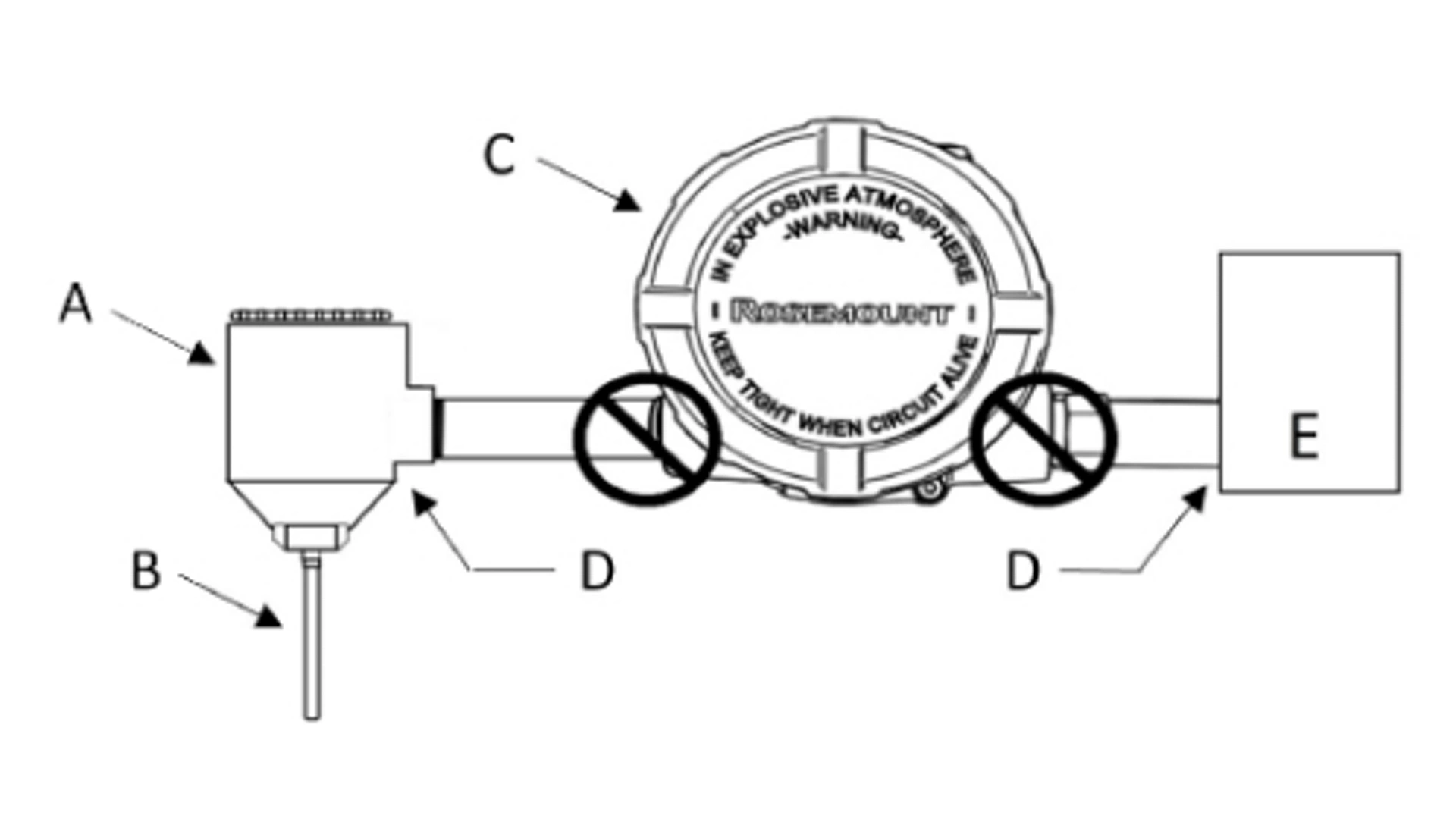
Emerson recommends this option for ungrounded transmitter housing.
A: Remote sensor housing
B: Sensor
C: Transmitter
D: Shield ground points
E: Distributed control system (DCS)
Procedure
1. Connect signal wiring shield to the sensor wiring shield.
2. Ensure the two shields are tied together and electrically isolated from the transmitter housing.
3. Ground shield at the power supply end only.
4. Ensure the shield at the sensor is electrically isolated from the surrounding fixtures that may be grounded.
5. Connect shields together, electrically isolated from the transmitter.
2. Standard Configuration
2.1 Configuration Overview
This section contains information on commissioning and tasks that must be performed on the bench prior to installation, as well as tasks performed after installation. This section also provides instructions on configuring using any communication device, including:
- Communication device, such as AMS Trex
- HART® host, such as AMS Device Manager
- AMS Device Configurator Bluetooth® app
- Quick Service Buttons
2.1.1 Configuring with a communication device
For more detailed information about AMS Trex, see AMS Trex Device Communicator. It is critical that the latest device descriptors (DDs) are loaded onto the communication device to ensure full functionality.
2.1.2 Configuring using AMS Device Manager
For more detailed information about AMS Device Manager, see the AMS Device Manager product page. It is critical that the latest device descriptors (DDs) are loaded onto the AMS Device Manager to ensure full functionality.
2.1.3 Configuring using the AMS Device Configurator Bluetooth® app
For more detailed information about the AMS Device Configurator Bluetooth app, see Configure via Bluetooth® wireless technology.
2.1.4 Configuring using the Quick Service buttons
You can use the Quick Service buttons for the following configuration and maintenance tasks:
- View Configuration shows the current device configuration.
- ReadyConnect Technology detects the sensor type, number of sensor wires, and Callendar-Van Dusen coefficients of a connected Rosemount 214C ReadyConnect-enabled temperature sensor. With a push of a button in the quick service buttons menu, the transmitter automatically updates to match the sensor details, allowing for quick, easy, and error-free configuration
- Sensor Configuration provides the ability to locally configure temperature sensor parameters into the transmitter to ensure accurate measurement.
- Loop Test will verify that the 4-20 mA loop is working properly. This is a common task performed prior to commissioning the transmitter.
- Rotate Display provides the ability to rotate the transmitter display in 90-degree increments to ensure proper display orientation.
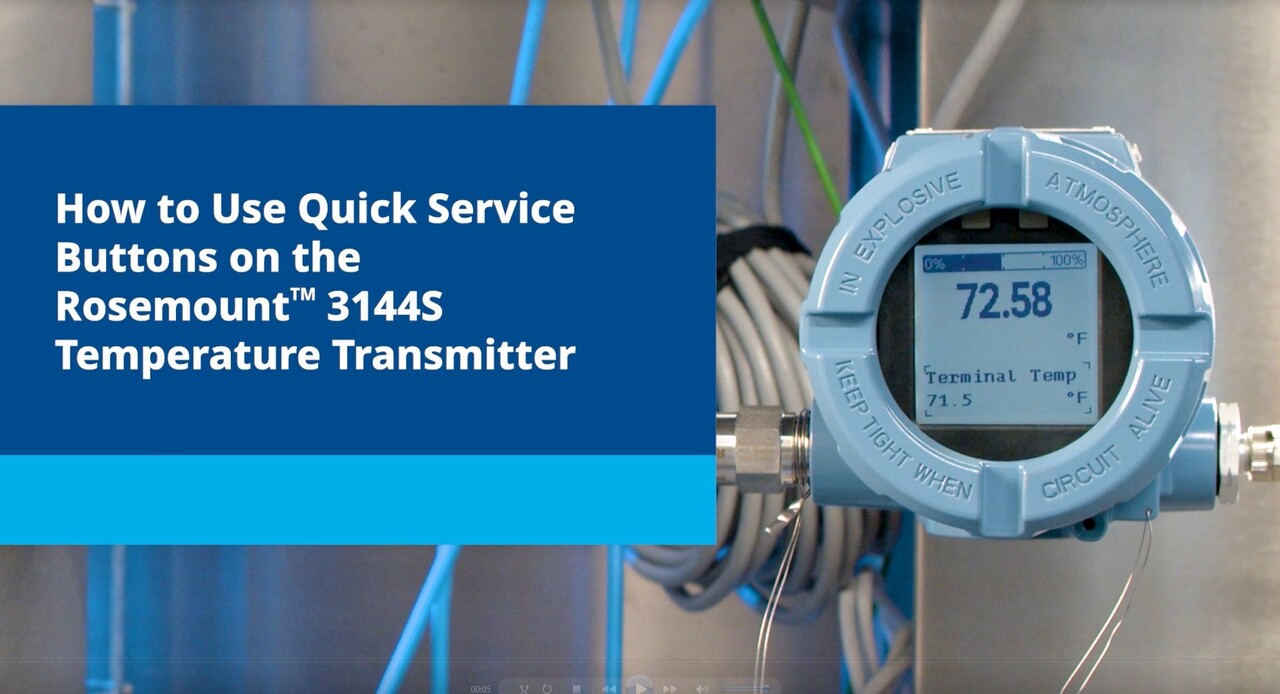
Quick Service Buttons are located on the LCD display. The housing cover must be removed to access the Quick Service Buttons. Hold both buttons for 3 seconds to enter the Quick Service Buttons menu. See the image on the right for button location.
2.2 Configuration
The transmitter must have certain basic variables configured to operate. In many cases, Emerson pre-configures these variables at the factory. The operator may need to configure the transmitter if they need to revise the configuration variables. For a list of the factory default variable settings, see the PDF manual. You may need to configure the transmitter to revise the configuration variables.
Before operating the transmitter in an actual installation, review all the factory-set configuration data to ensure that it reflects the current application. To review these parameters:
1. Go to Device Settings → Setup Overview
2. This will display device and security information, details for Measurement 1 and Measurement 2, alarm and saturation values, and current device output information (primary variable and damping).
Setup Overview enables users to perform all basic setup functions without having to access multiple screens and menus in the user interface. All basic device configuration information is located in one central spot, meaning that for simple configuration applications, a user may only need to visit this one screen to have a functional device.
To verify configuration using the Quick Service Buttons:
1. Locate the Quick Service buttons.
2. Hold both buttons for 3 seconds until the menu appears.
3. Use the buttons to navigate to the View Config screen.
4. Select Next to navigate through the screens and view the parameters.
5. Select Done to return to the main menu.

Bluetooth® wireless technology enables faster commissioning and improved ease of use. To connect to the device with Bluetooth technology:
1. Launch AMS Device Configurator. See AMS Device Configurator for Emerson Field Devices.
2. Select the device where you want to connect.
3. On first connection, enter the key for selected device. See figure below.
4. At the top left, select the menu icon to navigate the desired device menu.
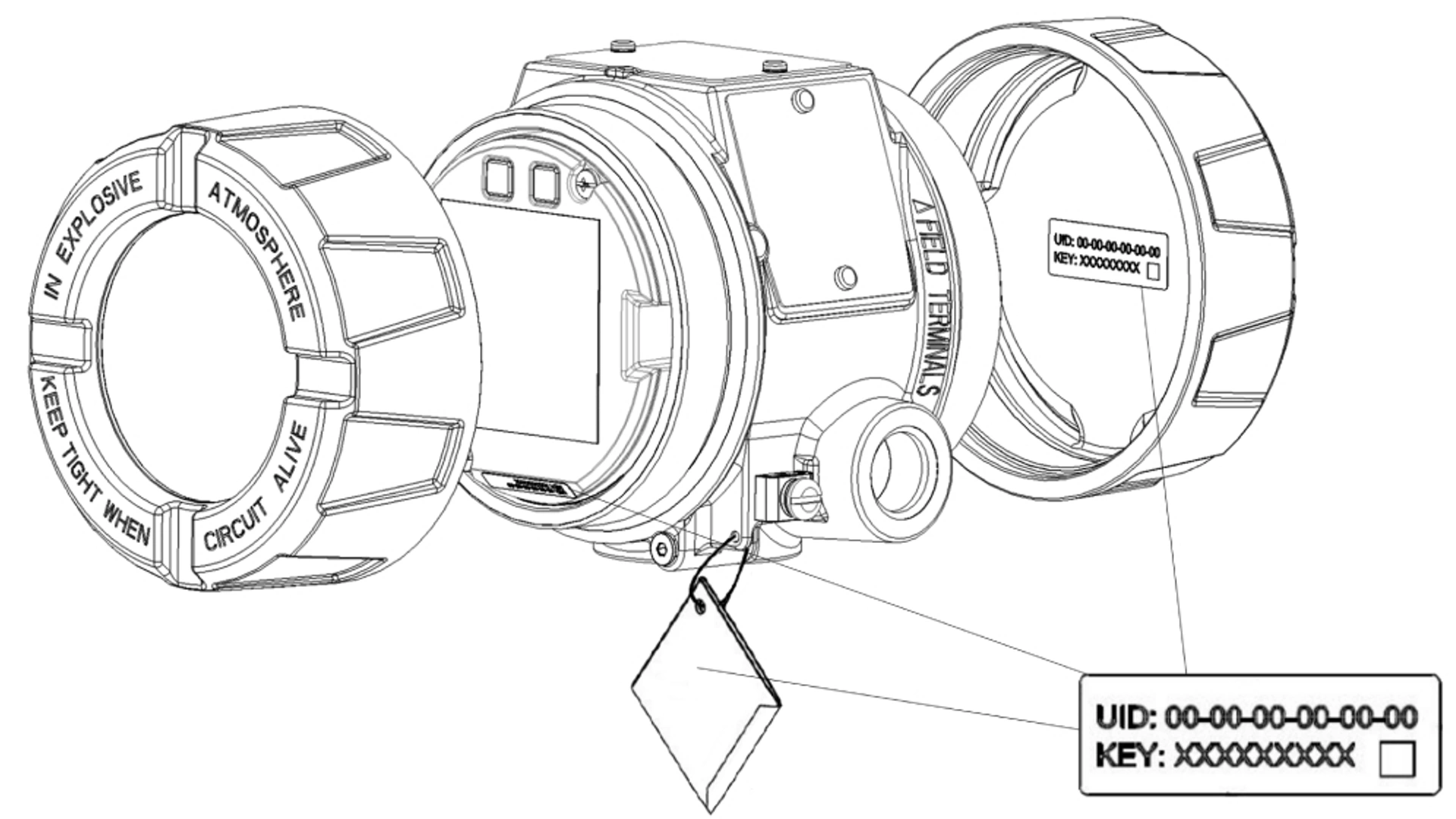
The UID (Unique Identifier) is the identification number unique to the Bluetooth radio on the device. The UID will be advertised when Bluetooth functionality is enabled on the output board. The Key is the required passkey to access the device. The information is only available in the tags located as shown in the figure above. Emerson does not retain copies of this information.
You can find the UID and Key in the following locations:
- Disposable paper tag attached to the device
- Label inside the terminal block cover
- Label on the display unit
Bluetooth comes configured from the factory. To disable Bluetooth communication:
- Go to Device Settings → Communication → Bluetooth
- Under Radio, select the dropdown menu, then select Disable
- To re-enable, select the dropdown menu, then select Enable
Each sensor must be properly configured for the correct sensor type and connection to ensure the best accuracy. To change the sensor type, connection, or units:
- Go to Device Settings → Setup Overview
- Under Measurement 1 or Measurement 2, the sensor type, connection, and units are displayed
- To change the sensor type, connection, or units, select the drop-down menu for the parameter(s) to be changed, then select the new value.
The following sensor types and connections are available:
- 2-, 3-, or 4-wire Pt 100, Pt 200, Pt 500, Pt 1000 (platinum) RTDs (α = 0.00385 Ω/Ω/°C)
- 2-, 3-, or 4-wire Pt 100 (platinum) RTDs (α = 0.00385 Ω/Ω/°C) with Callendar-Van Dusen
- 2-, 3-, or 4-wire Pt 100, Pt 200 (platinum) RTDs (α = 0.003916 Ω/Ω/°C)
- 2-, 3-, or 4-wire Pt 50, Pt 100 (platinum) RTDs (α = 0.00391 Ω/Ω/°C)
- 2-, 3-, or 4-wire Ni 120 (nickel) RTDs
- 2-, 3-, or 4-wire Cu 50, Cu 100 (copper) RTDs (α = 0.00426 Ω/Ω/°C)
- 2-, 3-, or 4-wire Cu 50, Cu 100 (copper) RTDs (α = 0.00428 Ω/Ω/°C)
- 2-, 3-, or 4-wire Cu 10 (copper) RTDs
- IEC/NIST Type B, E, J, K, N, R, S, T thermocouples
- DIN type L, U thermocouples
- ASTM Type W5Re/W26Re thermocouple
- GOST Type L thermocouples
- –10 to 100 millivolts
- 2-, 3-, or 4-wire 0 to 2000 ohms
- Rosemount X-well: standard and extended range
Contact an Emerson representative for information on temperature sensors, thermowells, and accessory mounting hardware that is available through Emerson.
The transmitter output can be set to one of the following engineering units:
- Degrees Celsius
- Degrees Fahrenheit
- Degrees Rankine
- Kelvin
- Ohms
- Millivolts
To configure a sensor using the Quick Service Buttons:
note
Only certain sensor types can be configured in this menu.
1. Locate the Quick Service buttons.
2. Hold both buttons for 3 seconds until the menu appears.
3. Use the buttons to navigate to the Sensor Config screen.
- Sensor types available in this menu include Pt100 RTD (a = 385), and Type J, K, E, and T thermocouples
4. Follow the prompts to configure the desired sensor. Select Done once complete to return to the main menu.
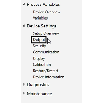
2.3 Device output configuration
Device output configuration contains PV range values, alarm and saturation and HART output. The user can set the transmitter’s lower and upper range values using limits of expected readings. The range of expected readings is defined by the Lower Range Value (LRV) and Upper Range Value (URV). The transmitter range values may be reset as often as necessary to reflect changing process conditions. To change either range limit:
1. Go to Device Settings → Setup Overview
2. Under Output, select Upper or Lower Range Value and enter the desired value
Reranging the transmitter sets the measurement range to the limits of the expected readings, which maximizes transmitter performance; the transmitter is most accurate when operated within the expected temperature range for the application.
Changing the rerange values on the transmitter should not be confused with performing a sensor trim. Although re-ranging the transmitter matches a sensor input to a 4–20 mA output, as in conventional calibration, it does not affect the transmitter’s interpretation of the input.
Damping changes transmitter's response time to smooth variations in output readings caused by rapid changes in input.
Determine the appropriate damping setting based on the necessary response time, signal stability, and other requirements of the loop dynamics of the system.
When set to zero, the damping function is off, and the transmitter output reacts to changes in input as quickly as the intermittent sensor algorithm allows. Increasing the damping value increases transmitter response time.
The default damping value is five seconds, and the maximum damping value allowed is 60 seconds.
To set a damping value:
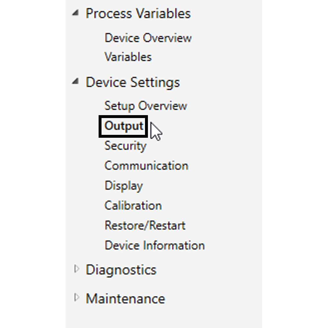
1. Go to Device Settings → Output → Measurement 1 or 2
2. Under Output, enter the desired damping value
If Measurement 1 or Measurement 2 is the primary variable, you change the damping by going to Device Settings → Setup Overview → Output
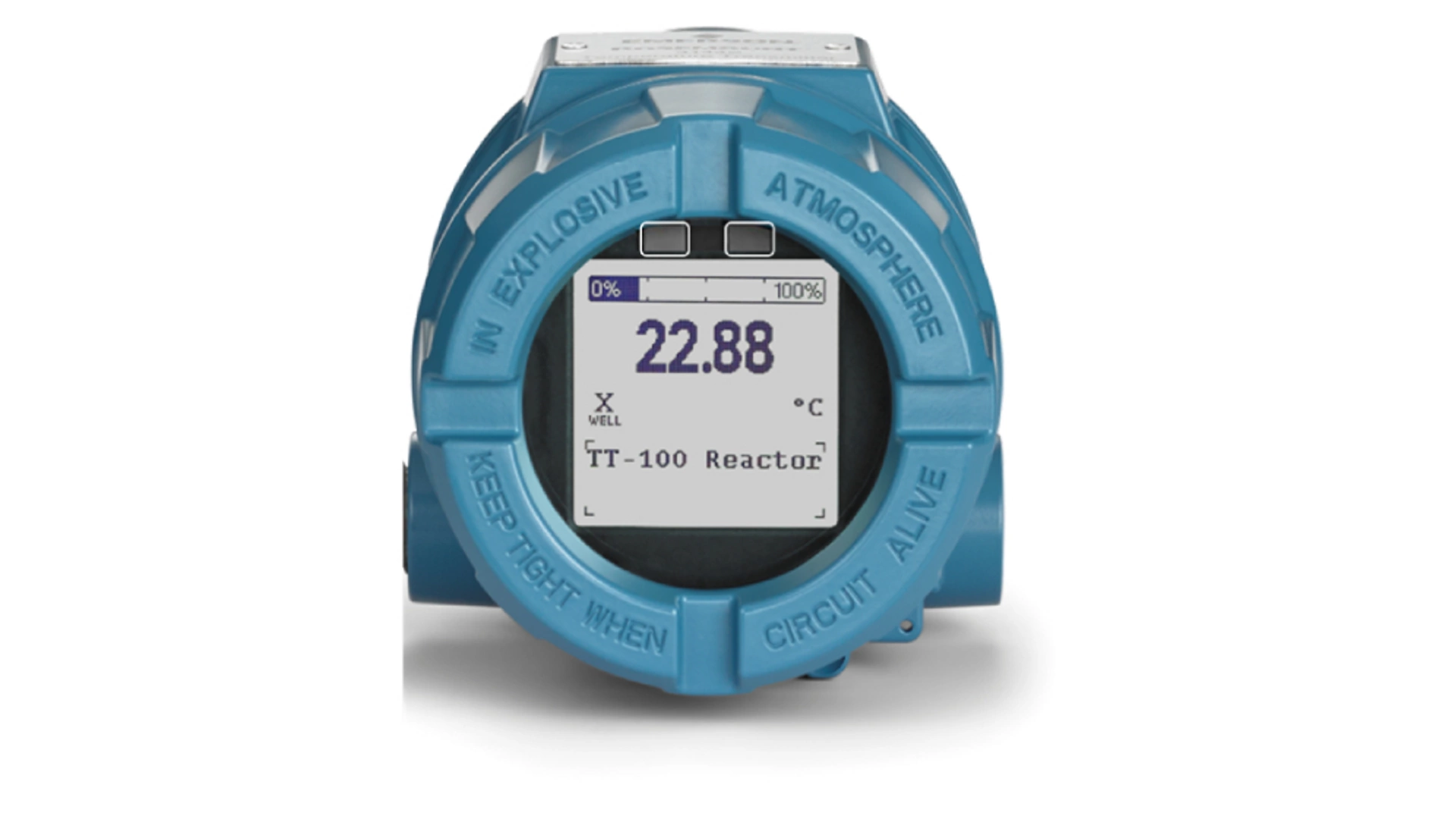
2.4 LCD display information
Local digital displays provide operators and maintenance staff with visibility to real-time process conditions, device status and diagnostic alerts at the measurement point without having to access or communicate with the control room.
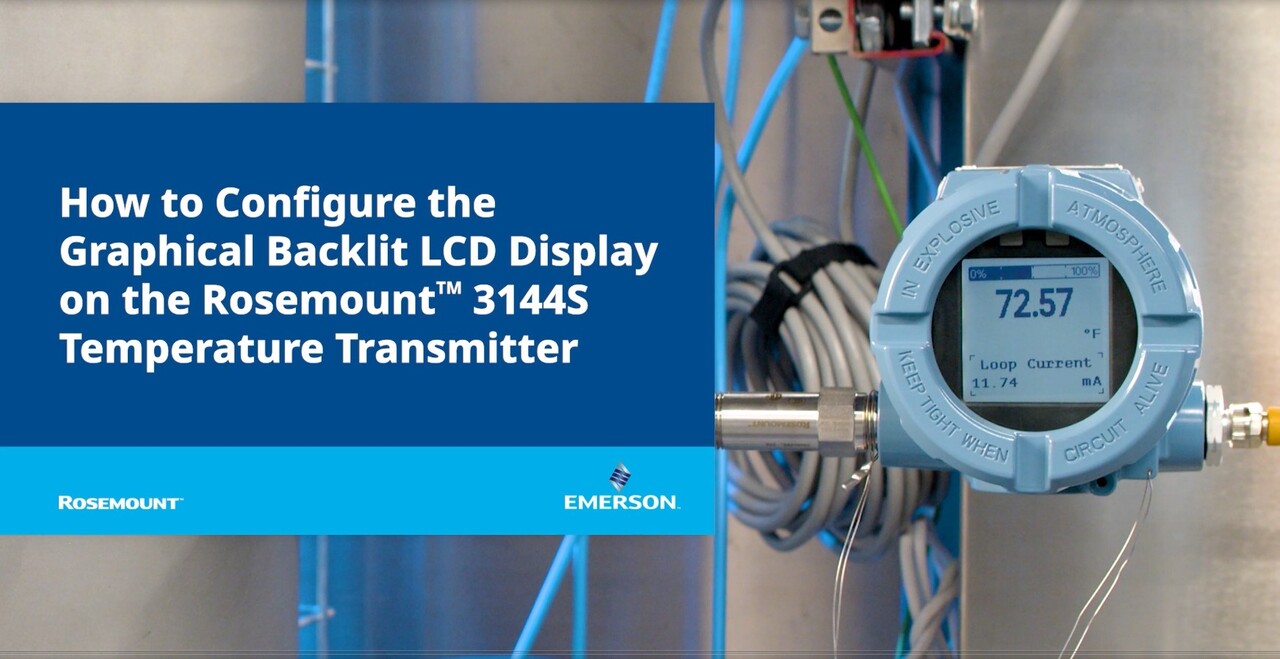
The Rosemount 3144S offers a graphical, backlit display that provides greater resolution and improved visibility. The graphical display enables both multilingual capability and the use of icons, including X-well and NE 107 status.
This display continually shows the primary variable, and a secondary area cycles through additional parameters selected. The LCD display settings can be changed to reflect necessary configuration parameters when adding an LCD display or reconfiguring the transmitter.
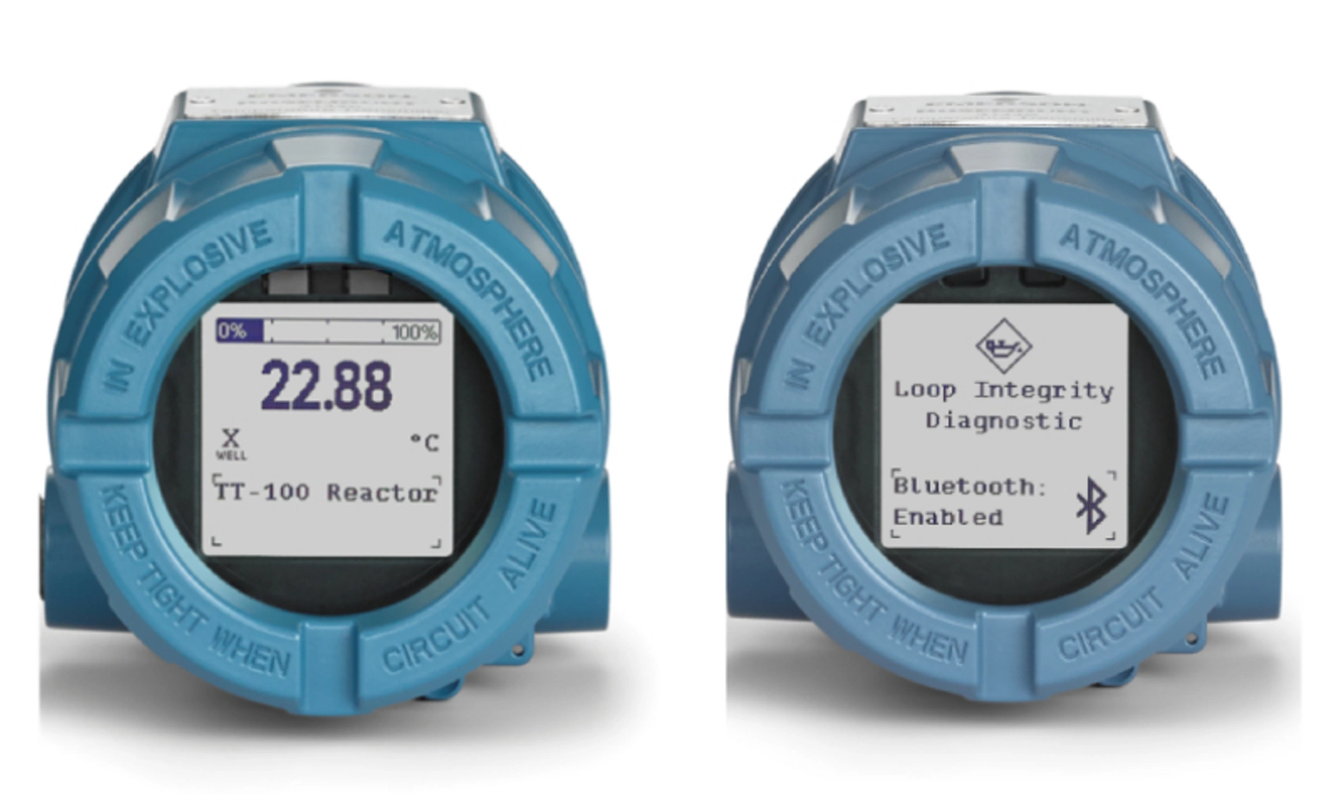
The LCD display contains two areas to give insight to process variables: the top area, which always displays the primary variable, and the bottom area, which cycles through additional parameters selected. To view or change the current parameters:
- Go to Device Settings → Display → Display
- Under Additional Parameters, the selected parameters are marked with a checked box
- To add or remove parameters, check or uncheck the box next to it
Additional parameters contain the following:
- Measurement 1
- Measurement 2
- Average Temperature
- Differential Temperature
- Loop Current
- Percent of Range
- Terminal Temperature
- Alarm Switch State
- Security Status
- HART Long Tag
- Bluetooth status
2.5 Device information
The following is a list of transmitter information variables, including device identifiers, factory-set configuration variables, and other information. A description of each variable is provided. The transmitter serial number, model code and Bluetooth radio UID (if applicable) are also shown in this menu. To view device information:
1. Go to Device Settings → Device Information → Identification
Tag: this is the easiest way to identify and distinguish between transmitters in multi-transmitter environments. Use it to label transmitters electronically according to the requirements of the application. The tag may be up to eight characters long and has no impact on the primary variable readings of the transmitter.
Long Tag: similar to Tag, but can be up to 32 characters instead of the eight characters in traditional Tag.
Date: a user-defined variable that provides a place to save the date of the last revision of configuration information. It has no impact on the operation of the transmitter.
Descriptor: provides a longer user-defined electronic label to assist with more specific transmitter identification than is available with the tag variable. The descriptor may be up to 16 characters long and has no impact on the operation of the transmitter.
Message: provides the most specific user-defined means for identifying individual transmitters in multi-transmitter environments. It allows for 32 characters of information and is stored with the other configuration data. The message variable has no impact on the operation of the transmitter.
2.6 Loop Test
The Loop Test action verifies the output of the transmitter, proper loop wiring, the integrity of the loop, transmitter output, and the operations of any recorders or similar devices installed in the loop. Only perform the Loop Test after you install the transmitter. To perform a loop test:
1. Go to Diagnostics → Simulation → Loop Test
2. Choose the Analog Output level and follow the prompts.
To perform a Loop Test using the Quick Service Buttons:
1. Locate the Quick Service buttons.
2. Hold both buttons for 3 seconds until the menu appears.
3. Use the buttons to navigate to the Loop Test screen.
4. Follow the prompts
5. Select Done to return to the main menu.
2.7 Device Restart and Device Configuration Reset
To restart the device or reset configuration parameters:
1. Go to Device Settings → Restore/Restart
2. Select:
- Device Restart to reset power to the device and preserve the current device configuration
- Device Configuration Reset to reset configuration parameters that affect the analog output and restart the device
3. Diagnostics Configuration
3.1 Diagnostics Overview
The Rosemount 3144S provides complete coverage from your temperature sensor to your control room with sensor health diagnostics, dual input capabilities, and continuous electrical loop monitoring. These capabilities help identify issues before they impact operations or compromise safety.
3.1.1 RTD Measurement Protection
RTD Measurement protection will seamlessly switch from a 4-wire to a 3-wire RTD sensor input configuration if one of the four sensor wires becomes broken, corroded, or loose anywhere from the sensor element to the transmitter terminal connections. The measurement will be maintained with no process disruption and a maintenance alert will be generated.
3.1.2 Thermocouple Degradation Diagnostic
The Thermocouple Degradation Diagnostic provides real time resistance monitoring of the thermocouple sensor loop, alerting operators of conditions that could indicate wire thinning, sensor degradation, moisture intrusion, or corrosion.
Degraded sensors/sensor wiring can result in measurement drift and inaccurate readings. By identifying these degraded conditions prior to failure, you can take action to prevent process downtime and protect against controlling your process based on incorrect values and possible unsafe conditions.
Once configured, the Thermocouple Degradation Diagnostic runs at least once per second, monitoring the resistance of the thermocouple sensor. As the resistance increases, the diagnostic can detect when the resistance exceeds the threshold. When this happens, the diagnostic will provide an alert. This feature is not intended to be a precise measurement of thermocouple status, but it is a general indicator of thermocouple sensor health by providing trending over time. The Thermocouple Degradation Diagnostic does not detect shorted thermocouples.
3.1.3 Hot Backup Capability
Hot Backup functionality requires dual-sensor configuration. In the event of a primary sensor failure, Hot Backup automatically switches from a failed sensor to a backup sensor without impact to the analog output signal. With Hot Backup configured as the primary variable, the transmitter shows the process alert and the temperature reading from the secondary sensor, so the analog output remains uninterrupted. This improves process availability by preventing a failure of the primary sensor from disrupting process control or causing a shutdown.
3.1.4 Sensor Drift Alert
Sensor Drift Alert requires dual-input configuration and can be used with both RTDs and thermocouples and provides real-time monitoring of the difference in temperature readings between a primary and secondary sensor.
The diagnostic will alert you via HART® alert or Analog Output alarm if the difference in temperature readings exceeds a user-defined threshold. By identifying a drifting sensor before it fails, you can take action to ensure you are operating with the most accurate temperature measurements at all times.
3.1.5 Loop Integrity
The Loop Integrity diagnostic detects issues that may jeopardize the health of the electrical loop. Issues may include:
- Water entering the wiring compartment and making contact with the terminals
- An unstable power supply nearing end of life
- Heavy corrosion on the terminals
The technology is based on the premise that once a transmitter is installed and powered up, the electrical loop has a baseline characteristic that reflects the proper installation. If the transmitter terminal voltage deviates from the baseline and outside the user-configured threshold, the transmitter can generate a HART® alert or analog alarm.
3.1.6 Process Alerts
Process Alerts allow you to configure the transmitter to output a HART® message when the configured threshold is exceeded.
You can set Process Alerts for any device variable. The transmitter will output a Process Alert if the monitored variable exceeds the user-defined threshold. An alert will be displayed on a Field Communicator, AMS Device Manager status screen, and the LCD display. The alert will reset once the value returns to within the range.
You do not need to set up the monitored variable as the primary variable, and you can set up each of the two available Process Alerts to monitor different variables if desired. You can also customize the name of each alert.
You can reference the Minimum/Maximum Tracking functionality at any time in the Process Alerts section. It is no longer a stand-alone diagnostic functionality.
3.2 RTD Measurement Protection
RTD Measurement Protection (formerly Ever Connect) automatically changes a 4-wire RTD sensor input configuration to 3-wire if a wire is broken or damaged, avoiding loss of measurement point while generating an alert.
This menu will only appear if the sensor is a 4-wire RTD. Once the sensor has been repaired, RTD Measurement Protection will automatically reset the device to read a 4-wire RTD. To configure RTD Measurement Protection:
1. Go to Device Settings → Output → Measurement 1 or 2 → Ever Connect
2. In the Configuration dropdown menu, select On.
To disable RTD Measurement Protection:
1. Go to Device Settings → Output → Measurement 1 or 2 → Ever Connect
2. In the Configuration dropdown menu, select Off.
LCD display message
The LCD display on the transmitter will display: “Sensor 1 Possible Lead Wire Loss” or “Sensor 2 Possible Lead Wire Loss.”
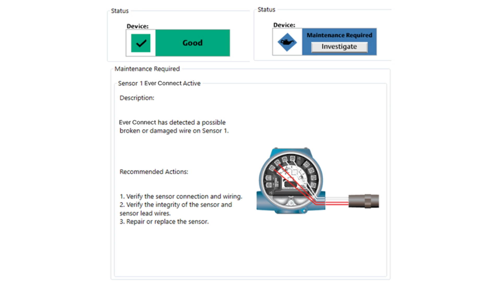
DD message
Under Process Variables → Device Overview → Status, the device status is listed. When both sensors are working properly, the status is shown as “Good.” When RTD Measurement Protection detects a loose, broken, or corroded sensor wire, the status is shown as “Maintenance Required.” Select the Investigate button to view more details, including recommended actions for fixing the issue. For RTD Measurement Protection, this will say: “Ever Connect has detected a possible broken or damaged wire on Sensor 1” or “Ever Connect has detected a possible broken or damaged wire on Sensor 2.”
3.3 Thermocouple Degradation Diagnostic
The Thermocouple Degradation Diagnostic acts as a gauge of general thermocouple health and is indicative of any major changes in the status of the thermocouple or the thermocouple sensor loop.
Once the sensor has been repaired and the sensor loop resistance returns to within the threshold limit, the Thermocouple Degradation Diagnostic will automatically reset.
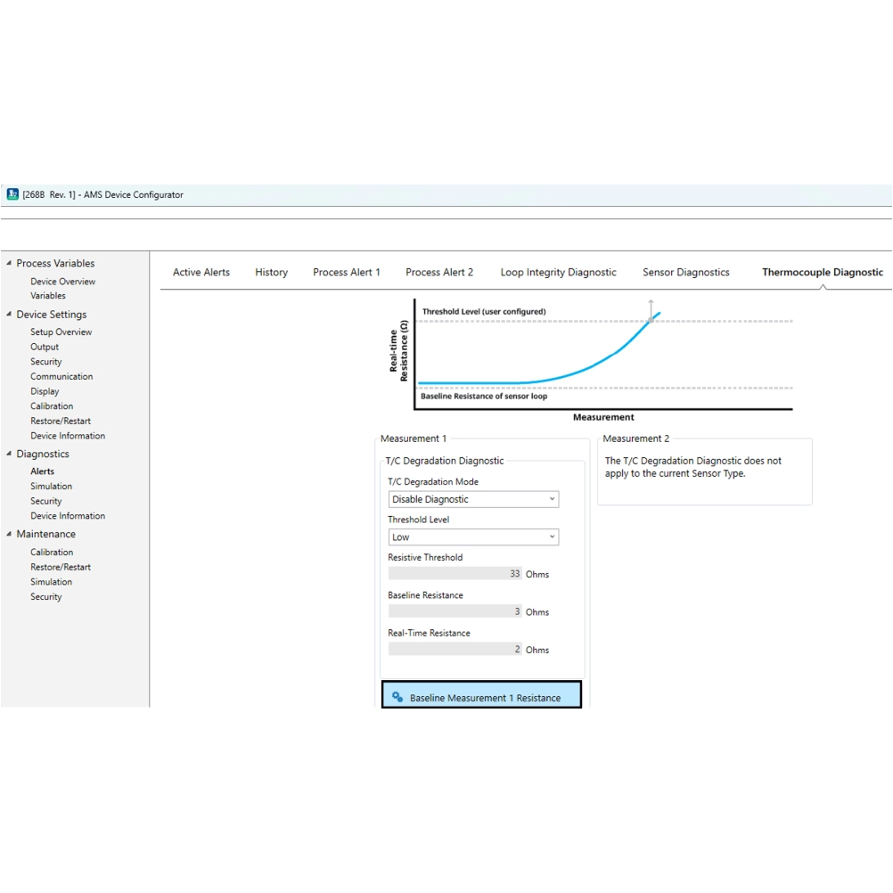
Your device must have Diagnostic Functionality "C" in the model code in order to utilize the Thermocouple Degradation Diagnostic. To configure Thermocouple Degradation Diagnostic:
1. Go to Diagnostics → Alerts → Thermocouple Diagnostic
2. Under Measurement 1 or Measurement 2 (whichever is a thermocouple), select Baseline Measurement 1 Resistance. The current sensor loop resistance will serve as the baseline.
3. Follow the prompts to continue. The resistance must be baselined in order to use the diagnostic. A new T/C Degradation Diagnostic menu will appear. This window displays the. T/C Degradation Mode, Threshold Level, Resistive Threshold, Baseline Resistance, and Real-Time Resistance
4. In the T/C Degradation Mode drop-down menu, select HART Status Alert.
5. The Threshold Level will default to Low. To change the Threshold Level, select the desired option from the Threshold Level drop-down menu. Options include:
- Low
- Medium
- High
- Custom
- If Custom Threshold Level is selected, a prompt opens requesting the desired Resistive Threshold value be entered.
To disable Thermocouple Degradation Diagnostic:
1. Select Diagnostics → Alerts → Thermocouple Diagnostic
2. Under the T/C Degradation Mode drop-down menu, select Disable Diagnostic
To verify Thermocouple Degradation Diagnostic is configured:
1. Go to Diagnostics → Alerts → Thermocouple Diagnostic
2. In the T/C Degradation Mode drop-down menu, HART Status Alert should be selected
LCD display messages
The LCD display on the transmitter will say “Sensor 1 Degraded” or “Sensor 2 Degraded.”
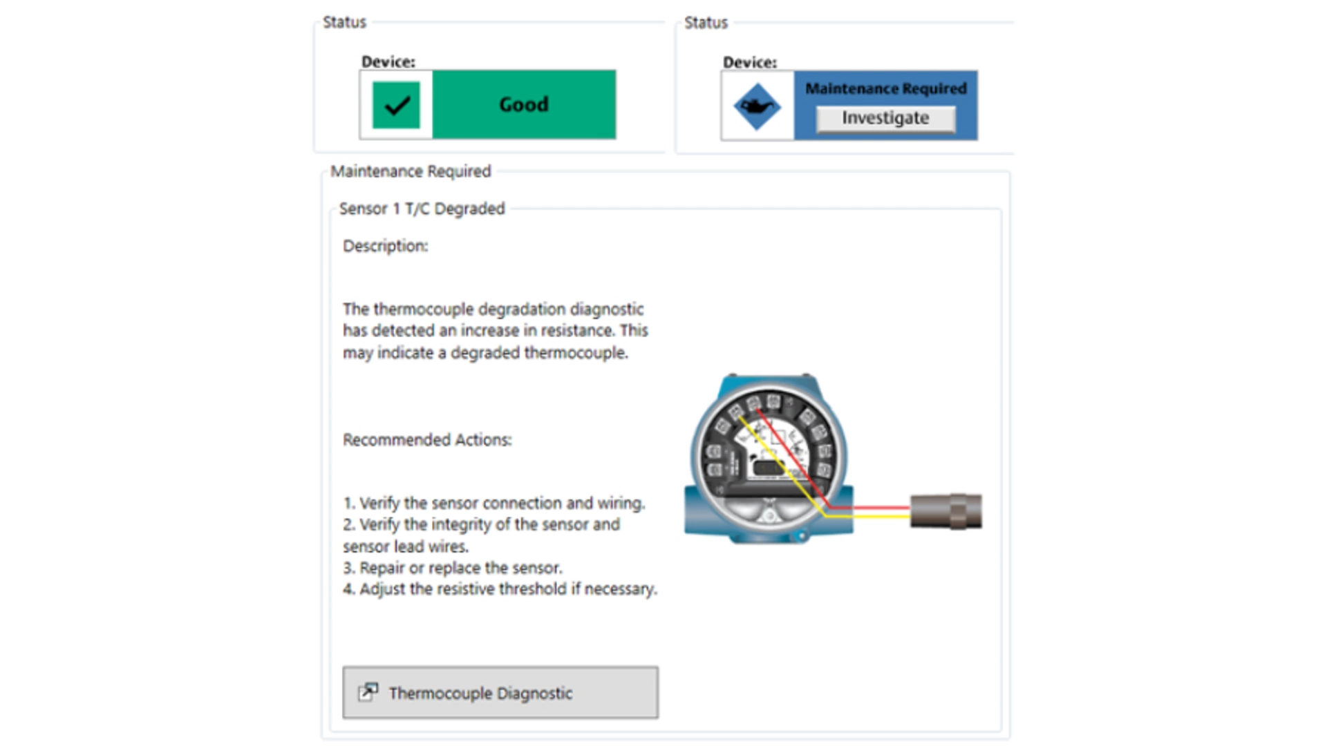
DD message
Under Process Variables → Device Overview → Status, the device status is listed. When both sensors are working properly, the status is shown as “Good.” When Thermocouple Degradation diagnostic is activated, the status is shown as “Maintenance Required.” Select the “Investigate” button to view more details, including recommended actions for fixing the issue. For Thermocouple Degradation diagnostic, this will say “The thermocouple degradation diagnostic has detected an increase in resistance. This may indicate a degraded thermocouple.”
3.4 Hot Backup Capability
The Hot Backup feature allows the transmitter to automatically use a secondary sensor as the primary sensor if the primary sensor fails, preventing process disruption due to a lost measurement. The Rosemount 3144S offers two variables that utilize the Hot Backup capability: Hot Backup and Average with Hot Backup.
Hot Backup is only enabled if either of these variables (Hot Backup or Average with Hot Backup) are selected as the PV. This differs from historic Hot Backup configuration on the Rosemount 3144P, where either First Good Temperature or Average Temperature was required to be the PV to utilize Hot Backup in addition to the general feature configuration.
When the PV is set to Hot Backup, the transmitter reading will be Measurement 1. If one of the sensors fail, an alert will be generated but the transmitter will continue to generate an output. Once the failed sensor is repaired, the alert will automatically reset.
When the PV is set to Average with Hot Backup, the output is the average of Measurement 1 and Measurement 2. If one of the sensors fail, an alert will be generated, and the transmitter output will represent the measurement that is still working. Once the failed sensor is repaired, the alert will automatically reset and the output will once again represent the average of the two readings.
If a sensor fails with either Hot Backup or Average with Hot Backup as the PV, the 4‑20 mA signal is not disrupted, and a status is sent to the control system (through HART® protocol) that the sensor has failed. An LCD display, if attached, displays the failed sensor status. If both sensors fail, the transmitter will go into alarm, and the status available (via HART) states that both Measurement 1 and Measurement 2 have failed.
To set Hot Backup as the PV:
1. Go to Device Settings → Setup Overview → Output
2. Under the Primary Variable dropdown menu, select Hot Backup or Average with Hot Backup.
To change the units of Hot Backup:
1. Go to Device Settings → Output → Calculated Outputs → Hot Backup Measurement → Setup
2. Select the desired units from the dropdown menu.
To change the units of Average with Hot Backup:
1. Go to Device Settings → Output → Calculated Outputs → Average Temperature → Setup
2. Select the desired units from the dropdown menu.
To view Hot Backup status:
1. Go to Device Settings → Output → Calculated Outputs
2. Verify the "Calculated Output Variables" dropdown displays "Enabled"
- Calculated Output Variables require 'Measurement 1' units, 'Measurement 2' units, 'Differential Temperature' units, 'Hot Backup Measurement' units, and 'Average Temperature' units to be selected as temperature units or the same raw unit (mV or Ohms).
3. View Hot Backup Measurement. Under Readings, the variable status is listed.
LCD display message
The LCD display message on the transmitter will cycle between displaying “Sensor 1 Failure” or “Sensor 2 Failure” and the output of the secondary sensor that has taken over the process.
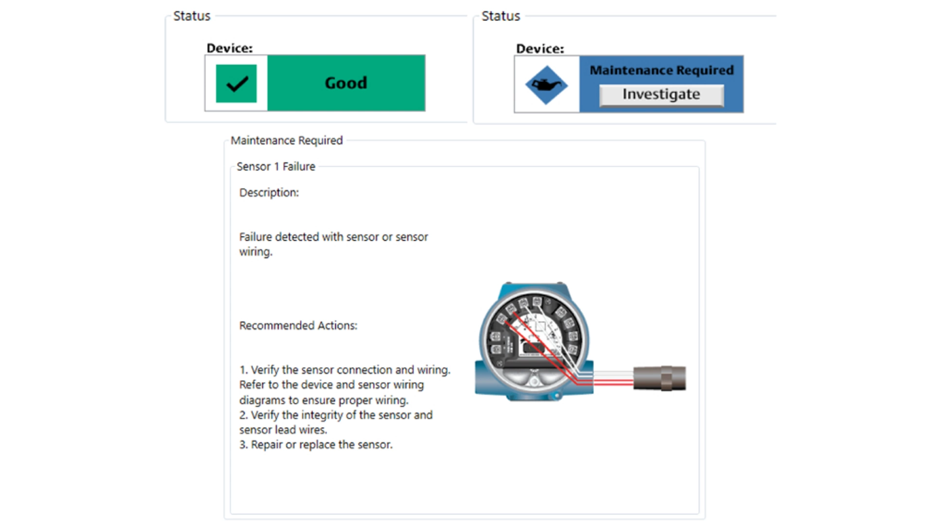
DD message
Under Process Variables → Device Overview → Status, the device status is listed. When both sensors are working properly, the status is shown as "Good" - see image on the right. When Hot Backup is activated, the status is shown as "Maintenance Required." Selecting the "Investigate" button provides more details, including recommended actions for fixing the issue. For Hot Backup, this will say "Failure detected with sensor or sensor wiring."
3.5 Sensor Drift Alert
The Sensor Drift Alert diagnostic allows the transmitter to set a warning status or go into analog alarm when the absolute value of the temperature difference between Measurement 1 and Measurement 2 exceeds a user-defined limit. Sensor Drift Alert does not indicate which sensor is failing, rather the diagnostic provides an indication of a sensor drifting. To determine which sensor is failing, the user should view the individual sensor output trends. Once the sensor has been repaired or the temperature difference between the sensors no longer exceeds the threshold, Sensor Drift Alert will automatically reset.
To configure Sensor Drift Alert:
1. Go to Diagnostics → Alerts → Sensor Diagnostics → Sensor Drift Alert
2. From the Mode drop-down menu, select either HART Status Alert (warning mode) or Analog Output Alarm (alarm mode)
3. Under Threshold, enter the desired temperature differential prior to triggering Sensor Drift Alert
4. Under Damping, enter the desired damping value for Sensor Drift Alert
To disable Sensor Drift Alert:
1. Go to Diagnostics → Alerts → Sensor Diagnostics → Sensor Drift Alert
2. Under the Mode drop-down menu, select Disable Alert
To verify Sensor Drift Alert is configured:
1. Go to Diagnostics → Alerts → Sensor Diagnostics → Sensor Drift Alert
2. In the Mode drop-down menu, either HART Status Alert (warning mode) or Analog Output Alarm (alarm mode) is selected if Sensor Drift Alert is configured
LCD display message
The LCD display on the transmitter will cycle between displaying "Sensor Drift Alert" and the current PV output.
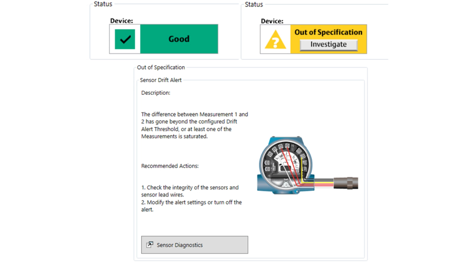
DD message
Under Process Variables → Device Overview → Status the device status is listed. When both sensors are working properly, the status is shown as "Good" - see image on the right. When Sensor Drift Alert is activated, the status is shown as "Out of Specification." Selecting the "Investigate" button provides more details, including recommended actions for fixing the issue. For Sensor Drift Alert, this will say "The difference between Measurement 1 and 2 has gone beyond the configured drift threshold, or at least one of the Measurements is saturated."
3.6 Loop Integrity
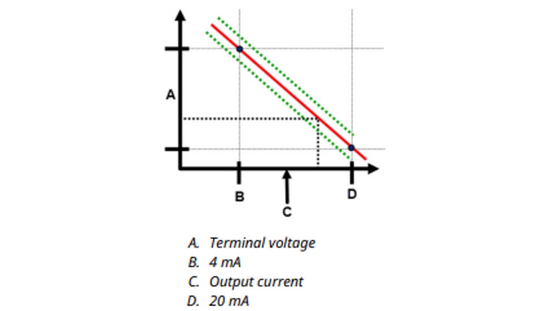
Emerson ships the transmitter with Loop Integrity off as default and without any loop characterization performed. Once you have installed and powered up the transmitter, you must perform a loop characterization for the Loop Integrity diagnostic to function. When you initiate a loop characterization, the transmitter will check to see if the loop has sufficient power for proper operation. Then the transmitter will drive the analog output to both 4 and 20 mA to establish a baseline and determine the maximum allowable terminal voltage deviation. Once this is complete, you enter a sensitivity threshold called Terminal Voltage Deviation Limit, and a check is in place to ensure this threshold value is valid. Once you have characterized the loop and set the Terminal Voltage Deviation Limit, the Loop Integrity diagnostic actively monitors the electrical loop for deviations from the baseline. If the terminal voltage has changed relative to the expected baseline value (exceeding the configured Terminal Voltage Deviation Limit), the transmitter can generate an alert or alarm.
note
The loop integrity diagnostic in the Rosemount 3144S Temperature Transmitter monitors and detects changes in the terminal voltage from expected values to detect common failures. It is not possible to predict and detect all types of electrical failures on the 4-20 mA output. Therefore, Emerson cannot absolutely warrant or guarantee that the loop integrity diagnostic will accurately detect failures under all circumstances.
To use the diagnostic, first create a baseline characteristic for the electrical loop after installing the transmitter. The loop is automatically characterized with the push of a button. This creates a linear relationship for expected terminal voltage values along the operating region from 4-20 mA.
1. Go to Diagnostics → Alerts → Loop Integrity Diagnostics →Configure Loop Integrity
2. The following message will appear: “Warning – Loop should be removed from automatic control.” Select Next, then select Next again to perform a loop characterization
3. Enter the desired Voltage Deviation Limit (+/-) that is tolerated before Loop Integrity Diagnostic is triggered. Then select Next
4. Enter the desired Notification Mode: select from Disable Diagnostic (no alert), HART Status Alert, or Analog Output Alarm, then select Next.
5. Select Next → Next → Finish on the following screens to complete the configuration and close the dialogue box.

LCD display message
The LCD display on the transmitter will display “Loop Integrity Diagnostic.”
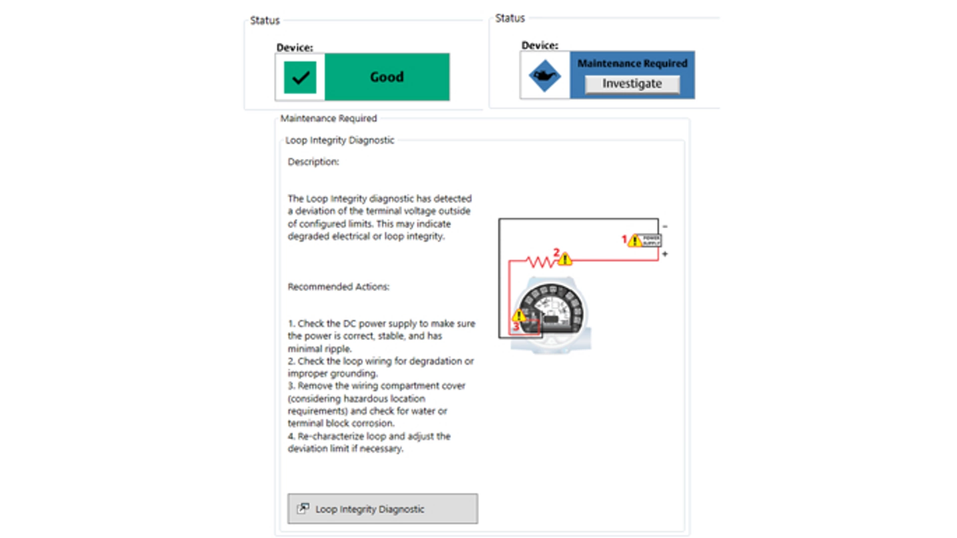
DD message
Under Process Variables → Device Overview → Status, the device status is listed. When the loop is working properly, the status is shown as “Good.” When the Loop Integrity diagnostic detects a change in the loop, the status is shown as “Maintenance Required.” Select the “Investigate” button to view more details, including recommended actions for fixing the issue. For Loop Integrity diagnostic, this will say "The Loop Integrity diagnostic has detected a deviation of the terminal voltage outside of configured limits. This may indicate degraded electrical or loop integrity.”
This field shows the current terminal voltage value in volts. the terminal voltage is a dynamic value and is directly related to the mA output value. To view the terminal voltage and terminal voltage deviation:
1. Go to Diagnostics → Alerts → Loop Integrity Diagnostics → Settings
3.7 Process Alerts
There are two process alerts that you can configure to use with any of the following variables:
- Measurement 1
- Measurement 2
- Terminal Temperature
- Hot Backup
- Differential Temperature
- Average Temperature
- Sensor 1(1)
- Sensor 2(1)
(1) Only available with X-well Technology devices.
The process alerts are independent of each other. You can use these alerts to receive notifications via HART Status Alert or via Analog Output alarm. Process alerts can be triggered with any variable, regardless of HART® variable assignments. This means an Analog Output Alarm can be triggered by any of the process variables listed previously, even if they are not assigned to be the HART primary variable.
The Minimum/Maximum Tracking functionality is now embedded in the process alerts. The minimum and maximum values will be recorded for the variables selected in the configured process alerts. These values will be recorded for the minimum and maximums obtained since the last reset; this is not a logging function.
To configure a process alert:
1. Go to Diagnostics → Alerts → Process Alert 1 or 2 → Alert Settings → Configure Process Alert 1 or 2.
2. Select the desired notification mode (HART Status Alert or Analog Output Alarm).
3. Select the desired variable from the Variable drop-down menu.
4. Select when to activate Process Alert from the following:
- Above high side
- Below low side
- Outside window
- Inside window
5. Set the High and Low alert values as applicable.
6. Select method for reducing sporadic alerts:
- None
- Deadband (refers to specifying the region from the alert value where alert deactivation will not occur)
- Time delay (refers to specifying an amount of time the alert must stay active before the device will report the alert)
7. Set the Alert Name.
4. Operation & Maintenance
4.1 Calibration
Calibrating the transmitter increases the precision of the measurement system. The user may use one or more of several trim functions when calibrating. To understand the trim functions, it is necessary to realize that HART Protocol transmitters operate differently from analog transmitters. An important difference is that smart transmitters are factory-characterized: they are shipped with a standard sensor curve stored in the transmitter firmware. In operation, the transmitter uses this information to produce a process variable output, dependent on the sensor input. The trim functions allow the user to make adjustments to the factory-stored characterization curve by digitally altering the transmitter’s interpretation of the sensor input.
Calibration of the Rosemount 3144S Transmitter may include:
- Sensor input trim: Digitally alter the transmitter’s interpretation of the input signal
- Transmitter-sensor matching: Generates a special custom curve to match that specific sensor curve, as derived from the Callendar-Van Dusen (CVD) constants
- Output trim: Calibrates the transmitter to a 4–20 mA reference scale
- Scaled output trim: Calibrates the transmitter to a user-selectable reference scale
4.2 Trim the transmitter
The trim functions should not be confused with the rerange functions. Although the rerange command matches a sensor input to a 4–20 mA output—as in conventional calibration—it does not affect the transmitter’s interpretation of the input.
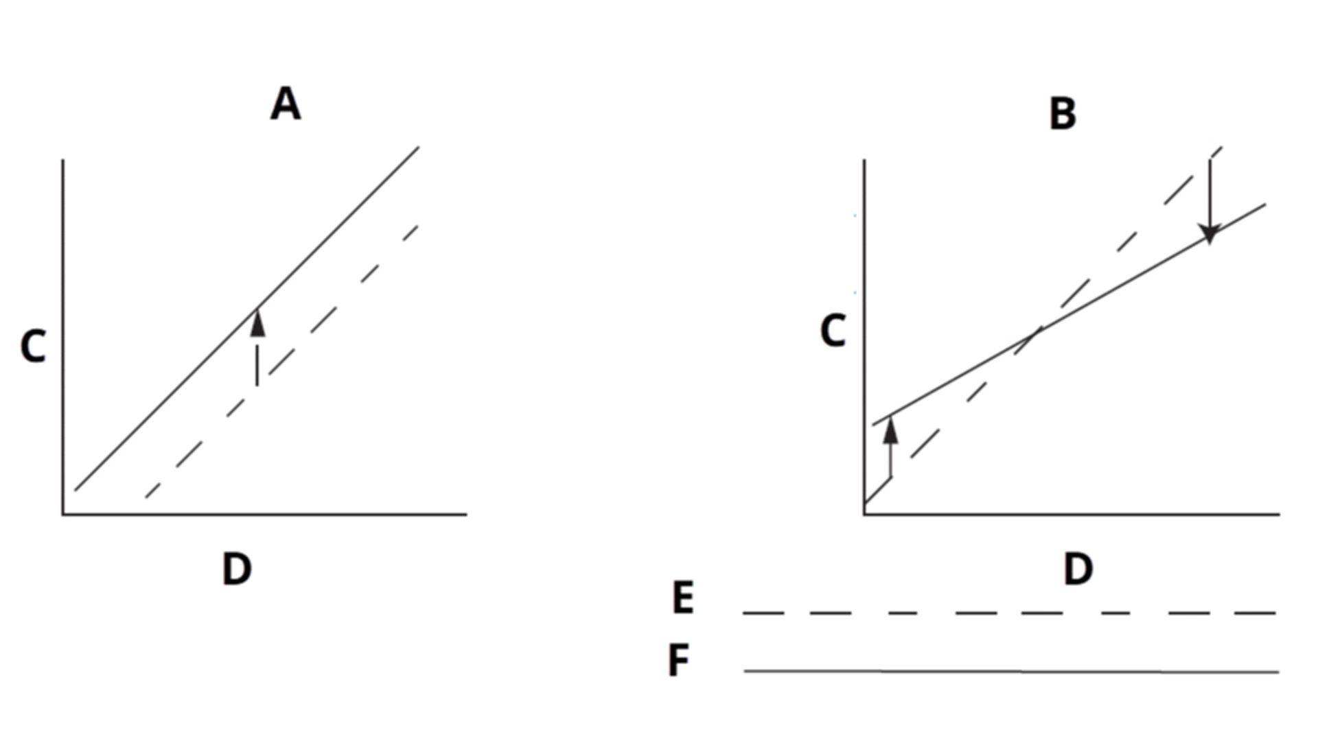
A. Single-point trim
B. Two-point trim
C. Raw measurement (Ohms or mV)
D. Temperature
E. Transmitter system curve
F. Site-standard curve
Sensor Input Trim
The Sensor Trim function allows for alteration of the transmitter’s interpretation of the input signal as shown in the graphs above. The sensor trim function trims, in engineering (°F, °C, °R, K) or raw (W, mV) units, the combined sensor and transmitter system to a site standard using a known temperature source. Sensor trim is suitable for validation procedures or for applications that require profiling the sensor and transmitter together. Perform a sensor trim if the transmitter’s digital value for the primary variable does not match the plant’s standard calibration equipment. Unless the site-standard input source is National Institute of Standards and Technology (NIST)-traceable, the trim functions will not maintain the NIST-traceability of your system.
To perform a Lower Trim :
1. Go to Maintenance → Calibration → Sensor 1 or Sensor 2.
2. Under Calibration, select Lower Sensor 1 or 2 Trim.
3. Follow the prompts to complete the sensor trim.
To perform an Upper Trim:
1. Go to Maintenance → Calibration → Sensor 1 or Sensor 2.
2. Under Calibration, select Upper Sensor 1 or 2 Trim.
3. Follow the prompts to complete the sensor trim.
Disable Sensor Pulsing
The transmitter operates with a pulsing sensor current in order to perform sensor diagnostics and while switching between multiple sensors. Although it is becoming less common, some calibration equipment requires a steady sensor current to function properly. You can accomplish this within the transmitter by disabling the sensor pulsing functionality during calibration.
Disabling sensor pulsing temporarily sets the transmitter to provide steady sensor current to a single sensor during calibration. During that time, the other sensor will be temporarily disabled, and some sensor diagnostics will not function. Ensure sensor pulsing is reenabled before putting the transmitter back into the process. Disabled Sensor Pulsing status is volatile and will automatically be re-enabled when a master reset is performed (through HART® protocol) or when the power is cycled. If sensor pulsing is not re-enabled or transmitter is not reset or power-cycled, it will automatically re-enable after a 60-minute timeout in the transmitter.
Transmitter-sensor matching
The transmitter accepts Callendar-Van Dusen (CVD) constants from a calibrated RTD schedule and generates a special custom curve to match that specific sensor's resistance vs. temperature performance.
Matching the specific sensor curve with the transmitter significantly enhances the temperature measurement accuracy. The matching process allows the operator to enter four sensor-specific CVD constants into the transmitter. The transmitter uses these sensor-specific constants in solving the CVD equation to match the transmitter to that specific sensor, thus providing outstanding accuracy.
The table below compares the total probable error of two assemblies: one with CVD matching, and one without.
System Accuracy Comparison at 150°C Using a Pt 100 (a=0.00385) RTD with a Span of 0 to 200°C
Matched RTD | Standard RTD | |
|---|---|---|
Transmitter Error | ±0.05°C | ±0.05°C |
Sensor Error | ±0.18°C | ±1.05°C |
Total Probable Error | ±0.19°C | ±1.05°C |
(1) Calculated using root-summed-squared (RSS) statistical method.
Output Trim or Scaled Output Trim
Perform a D/A output trim (scaled output trim) if the digital value for the primary variable matches the plant standard, but the transmitter’s analog output does not match the digital value on the output device (such as the ammeter). The output trim function calibrates the transmitter analog output to a 4–20 mA reference scale; the scaled output trim function calibrates to a user-selectable reference scale. To determine the need for an output trim or a scaled output trim, perform a loop test.
Output trim
Output Trim allows you to alter the transmitter's conversion of the input signal to a 4-20 mA output. Calibrate the analog output signal at regular intervals to maintain measurement precision.
1. Go to Device Settings → Calibration → Analog Output.
2. Under Calibration, select Analog Calibration.
3. Select Digital to Analog Trim.
4. Connect a reference meter to the device and follow the prompts.
Scaled output trim
Scaled Output Trim matches the 4 and 20 mA points to a user-selectable reference scale other than 4 and 20 mA (2 to 10 volts, for example). Before performing a Scaled Output Trim, ensure an accurate reference meter is connected to the transmitter.
1. Go to Device Settings → Calibration → Analog Output.
2. Under Calibration, select Analog Calibration.
3. Select Digital to Analog Trim.
4. Follow the prompts to complete the trim.
The AC Power Filter (also known as Line Voltage Filter or 50/60 Hz Filter) variable sets the transmitter electronic filter to reject the AC power supply frequency in the plant which can cause erroneous readings. You can set the filter to 50 Hz, 60 Hz, or a dual notch 50/60 Hz setting. The factory default for this setting is 60 Hz. To view or change the filter status:
1. Go to Device Settings → Output → Measurement Filtering
2. In the AC Power Filter drop-down menu, select one of the following:
- 50 Hz
- 60 Hz
- 50/60 Hz
4.3 Logging Capabilities
Logging is the process of collecting and storing data and/or events over a period of time. A variety of process and measurement data can be logged, including diagnostics, calibration history, and proof testing. In general, logging can help ensure compliance with industry specific regulations and quality and environmental control procedures, while also providing a historical record that can be used for troubleshooting and process optimization. The integrated logging functionality on the Rosemount 3144S creates and stores log entries for a variety of critical process and transmitter maintenance events. This functionality is designed to create a convenient means of accessing diagnostic, calibration and proof test logs at the device. These event ready logs can be accessed by connecting a communicator, such as an AMS Trex, AMS Device Manager or AMS Configurator, to the transmitter.
The calibration logging functionality arms users with the ability to access and manage prior calibration events locally at the device. When the transmitter undergoes any type of digital or analog calibration, the transmitter automatically captures the sensor and analog output trim adjustments, along with the sensor verifications when there is no trim needed; a correlated time stamp of this event is also logged at time of calibration. When accessing the calibration log, users will see calibration data organized in a stacked form with useful columns: time since last calibration event, what type of action was taken, source of interface, the value as found pre-event and the value as left post-event. The maximum number of individual calibration logs within the transmitter is 20 and will automatically delete on a first-in, first-out basis.
1. Go to Device Settings → Calibration → Sensor 1 or 2 → Calibration History
2. Select View Sensor 1 or 2 Calibration Log
To clear the calibration log:
1. Go to Device Settings → Calibration → Sensor 1 or 2 → Calibration History
2. Select Clear Sensor 1 or 2 Calibration Log
4.4 Maintenance
The transmitter has no moving parts and requires a minimum amount of scheduled maintenance and features a modular design for easy maintenance. If a malfunction is suspected, check for an external cause before performing the procedures discussed in this section.
warning
If the sensor is installed in a high-voltage environment and a fault condition or installation error occurs, the sensor leads and transmitter terminals could carry lethal voltages. Use extreme caution when making contact with the leads and terminals.
The test clips are the positive (+) and negative (-) clips in the center of the terminal block and accept Minigrabber® or alligator clips to facilitate in-process checks. The test clips are connected across a diode through the loop signal current. The current measuring equipment shunts the diode when connected across the test clips. So as long as the voltage across the clips is kept below the diode threshold voltage, no current passes through the diode. To ensure there is no leakage current through the diode while making a test reading or while an indicating meter is connected, make sure the resistance of the test connection or meter does not exceed 10 ohms. A resistance value of 30 ohms will cause an error of approximately 1.0 percent of reading.
5. Troubleshooting
This section provides summarized troubleshooting suggestions for the most common operating problems. If you suspect malfunction despite the absence of any diagnostic messages on the Field Communicator display, consider using the HART 4-20 Basic Troubleshooting tab below to identify any potential problem.
Symptom | Potential Source | Corrective Action |
|---|---|---|
Transmitter does not communicate with Field communicator | Loop wiring |
|
High output | Sensor input failure or connection |
|
High output | Loop wiring |
|
High output | Power supply |
|
High output | Electronics module |
|
Erratic output | Loop wiring |
|
Erratic output | Electronics module |
|
Low output or no output | Sensor element |
|
Low output or no output | Loop wiring |
|
Low output or no output | Electronics module |
|
6. Rosemount X-well Technology
Rosemount X-well Technology can only be utilized on devices that specify Measurement Functionality 3 or 4 in the model code.
6.1 Wiring for Rosemount X-well Technology
Wiring diagrams are located inside the terminal block cover. Emerson ships X-well assemblies from the factory pre-wired. Verify the sensor wiring matches the expected configuration (standard or extended range). Standard Range sensors are only available with direct mount configuration, and therefore must be wired to terminals 1-4 (single sensor configuration).
The Rosemount 3144S Temperature Transmitter can be wired and configured in the field with two independent remote mounted extended range sensors. This allows for dual input functionality such as Hot Backup™, differential temperature, average temperature, and diagnostic capabilities.
")
")
6.2 Installation for Rosemount X-well Technology
6.2.1 Technology Considerations
Rosemount X-well™ Technology is for temperature monitoring applications and is not intended for control or custody transfer applications. X-well Technology will only work as specified with factory-supplied and assembled pipe clamp sensors via the Rosemount 3144S or 214XW. It will not work as specified with other sensors.
note
Installing and using the incorrect sensor will result in inaccurate process temperature calculations.
It is important that you follow the preceding requirements and installation steps to ensure X-well Technology works as specified.
6.2.2 Installation Considerations
Follow pipe clamp sensor installation best practices as well as the specific Rosemount X-well™ Technology requirements noted below:
For X-well Technology to properly function with the Standard Range Sensor, it is necessary do directly mount the transmitter on a pipe clamp sensor. The image on the right displays a transmitter/pipe clamp assembly that is in a direct mount configuration.
Location and orientation
- Mount the clamp sensor on the outside section of the pipe where the process medium is in contact of the inside of the pipe wall.
- Ensure that the pipe surface is clean of debris.
- The pipe clamp sensor should be mounted in a secure position to ensure there is no rotational movement after installation.
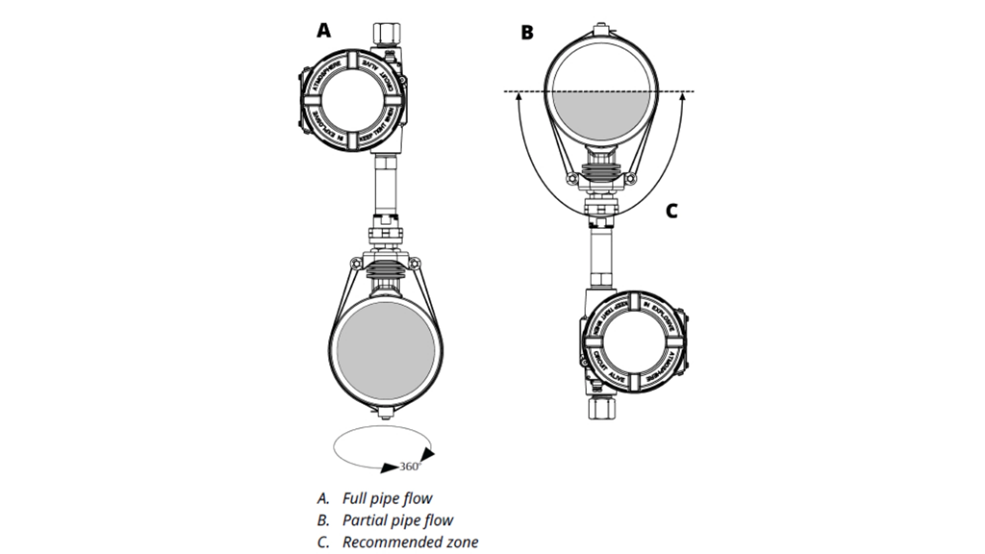
Emerson recommends mounting the pipe mount sensor on the upper half of the pipe. Only consider bottom mounting when there is partial pipe flow in order to maintain accurate measurement.
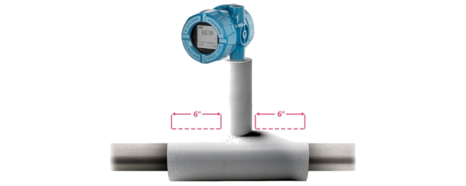
Insulation
- Install the assembly away from dynamic external temperature sources, such as a boiler or heat tracing.
- Ensure the pipe clamp sensor makes direct contact with the pipe surface. Moisture buildup between the sensor and the pipe surface or the sensor hangup in the assembly can cause inaccurate process temperature calculations.
- Insulation at least ½-inch (13 mm) thick (with R-value of > 0.42 m2 x K/W) is required over the sensor clamp assembly and the sensor extension to prevent heat loss. When using the standard range sensor, insulation should cover the entire sensor extension, up to the transmitter head. When using the extended range sensor, insulation should cover the nipple union of the extension. Apply a minimum of 6 in. (152 mm) of insulation on each side of the pipe clamp sensor. Take care to minimize air gaps between insulation and pipe.
6.2.3 Universal Pipe Mount Installation

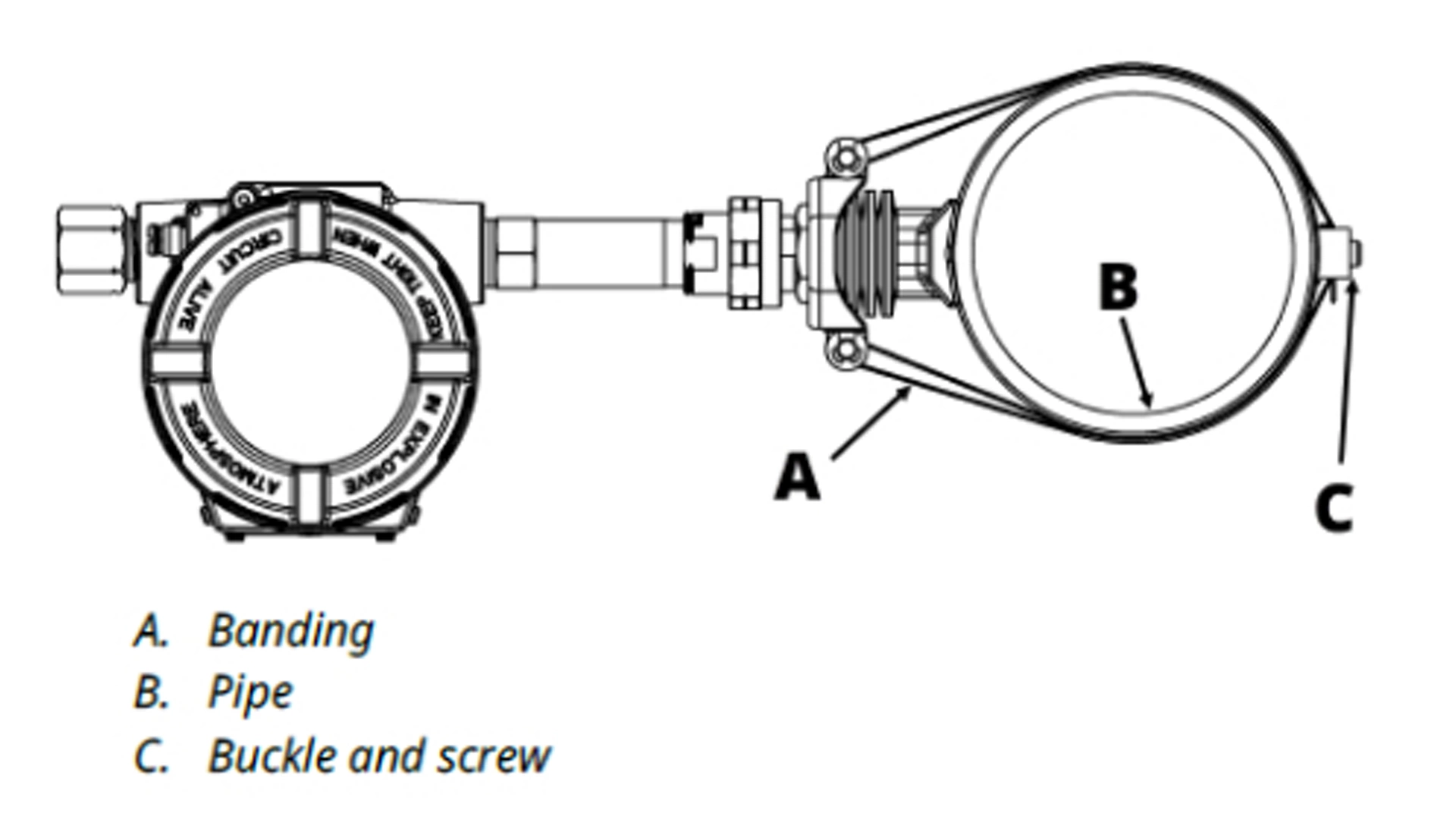
1. Place the mount foot onto the pipe surface; then run the banding around the pipe and through the inside of the tensioner plate, making sure that the screw side of the buckle is facing inward, as shown.
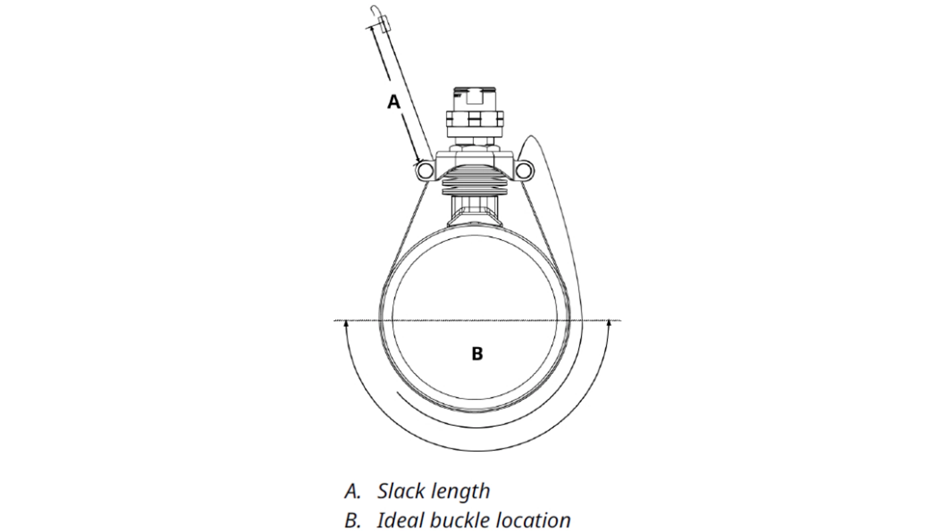
2. Bend the banding down around the rods of the tensioner plate. The end of the band with the buckle attached should be bent at a length that allows the buckle to sit near the bottom side of the pipe, opposite to the clamp assembly. Acceptable location for the buckle is anywhere on the lower half of the pipe, opposite to the clamp. The buckle must not fall within the distance between the tensioner plate and the pipe.
See the following tables for suggested slack length from buckle to bend over rod, based on line size.
Table 3-1: Imperial Slack Length
Pipe size |
Length to first bend (A) |
|---|---|
2 in. |
4.7 in. |
2.5 in. |
5.5 in. |
3 in. |
6.2 in. |
4 in. |
7.5 in. |
5 in. |
9 in. |
6 in. |
10.6 in. |
8 in. |
13.6 in. |
10 in. |
16.7 in. |
Table 3-2: Metric Slack Length
Pipe size |
Length to first bend (A) |
|---|---|
DN50 |
120 mm |
DN65 |
140 mm |
DN80 |
157 mm |
DN100 |
192 mm |
DN125 |
228 mm |
DN150 |
254 mm |
DN200 |
346 mm |
DN250 |
424 mm |
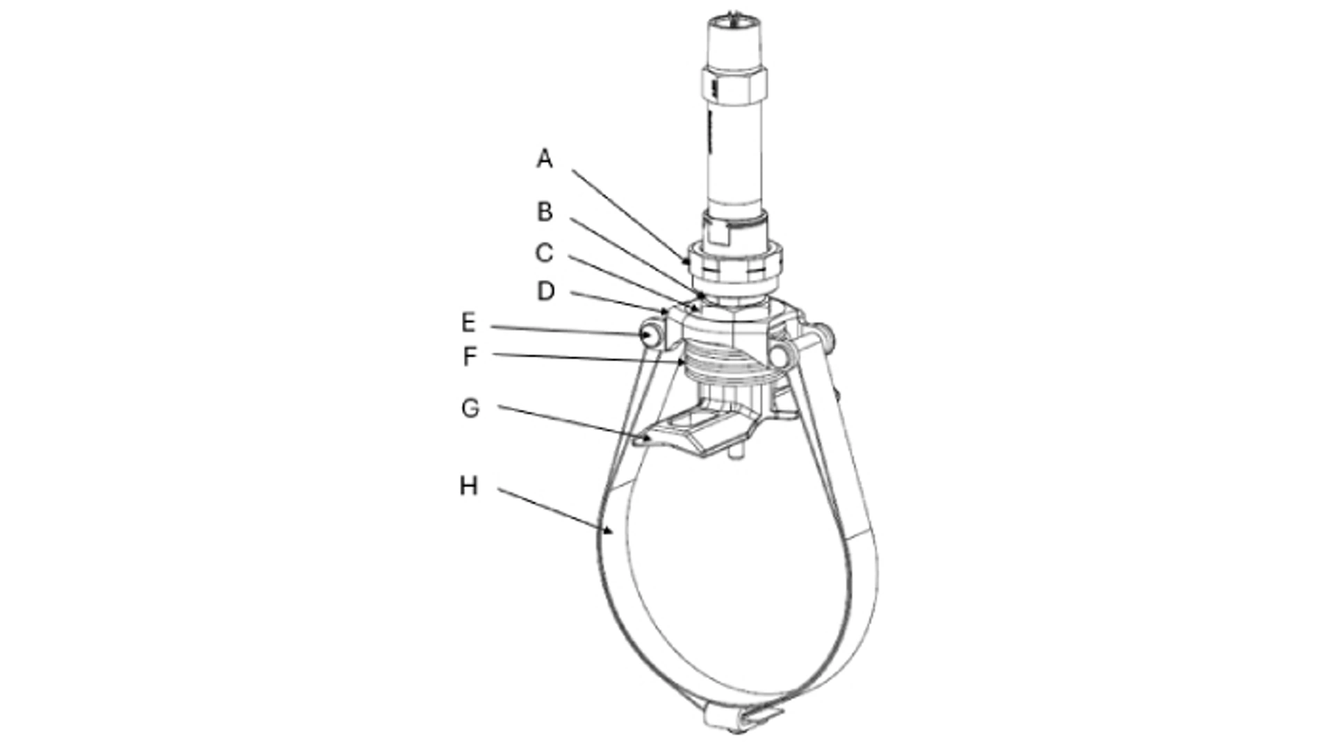
A. Union
B. Threaded stem
C. Tension nut
D. Tensioner plate
E. Removable tension rods
F. Springs
G. Mount foot
H. Banding and buckle
3. Wrap the free end of the band around the pipe and through the buckle. Fold back loose end at least 90° to temporarily secure the band in place. Then pull the banding snug and bend it so that it is perpendicular to the pipe.
4. Place banding within tensioner tool. Place nose of tensioner tool against the buckle, and slide banding into tool.
note
The position of the clamp assembly may be moved after the banding has been tensioned, so the clamp does not need to be in the final position during this step. Emerson recommends that the clamp be positioned to allow for the most ergonomic use of the tensioner tool for this step.
5. Turn the crank on the tensioner tool to tighten the banding. This will slowly compress the tensioner plate and spring.
6. Using a 4 mm Allen wrench, tighten the set screw on the buckle to lock the banding in place.
7. Once the banding is secured, reduce tension on the tensioner tool by spinning the crank counter-clockwise, and remove the tool. Then bend the loose end of the banding over top of the buckle.
note
Emerson recommends leaving enough length of banding to allow for re-tensioning of the banding if ever necessary. If you choose to trim any excess banding, be sure to remove any sharp edges or burrs.
8. With the banding tensioned, the clamp assembly may now be moved to its desired location. Using a 15/16-inch or 24 mm open-ended wrench, turn the tension nut clockwise on the threaded stem until it contacts the tensioner plate. Continue to tighten the tension nut to compress the springs until the banding loses tension and the clamp may be freely moved around the pipe.
9. Once the universal pipe mount is in its desired position, loosen the tension nut to decompress the spring to return tension to the banding. When loosening, return the tension nut to the top of the threaded stem.
If the universal pipe mount is properly installed, the distance from bottom of union stem head to top of tension plate should be set at 0.46 in. or 11.9 mm.
6.2.4 Uninstall and Re-install Pipe Mount
1. Using a 1 1/16-inch or 27 mm open-ended wrench, turn the tension nut clockwise on the threaded stem until it contacts the tensioner plate. Continue to tighten the tension nut to compress the springs until the banding loses tension and you can freely move the clamp around the pipe.
2. Using a pair of pliers, pull off each e-clip, and slide out each tension rod from the tensioner plate to remove the banding loop from the assembly. Reattach the tension rods and e-clips to the tensioner plate.
3. If reinstalling on the same pipe, reverse these steps to reassemble the universal pipe mount and form a banding loop. If reinstalling on a new pipe, proceed to Step 4.
4. If reinstalling on a new pipe, ensure top of tension nut is in line with bottom of black indicator mark before reinstallation. If it is not, put mount foot assembly in vice and adjust tension nut to correct height using a 1 1/16-inch or 27 mm open-ended wrench. If tension nut is at the correct height, proceed to standard installation instructions.
6.2.5 Small Pipe Mount Installation
Procedure
1. Place the mount foot assembly on the pipe with the slots running perpendicular to the pipe.
2. Insert U-bolt around the pipe and through the slots.
Emerson ships all Small Pipe Mounts with washers and spacers. For installation on line sizes ½-inch (DN15) to 1-inch (DN25), use only the spacer. For line sizes 1.25-inch (DN32) to 1.5-inch (DN40), use only the washer.
3. Place first washer/spacer through threads of U-bolt to sit on top of foot mount assembly; then loosely tighten nut onto the same U-bolt thread.
4. Repeat Step 3 for other side of U-bolt.
5. Incrementally tighten the nuts in an alternating manner until assembly sits squarely against the pipe.
6. Install transmitter and sensor assembly into foot mount assembly. Ensure sensor passes through hole of mount foot and has direct contact between the sensor tip and pipe. During sensor installation, stabilize the Small Pipe Mount by placing 29 mm or 1 1/8" wrench on the flats of the mount foot.
6.3 Configure Rosemount X-well Technology
Rosemount X-well Technology may come configured from the factory or be configured in the field. To configure Rosemount X-well Technology on the 3144S:
1. Go to Device Settings → Output
2. Select Measurement 1 if your X-well sensor is wired to Sensor Terminals 1-4, or Measurement 2 if wired to Sensor Terminals 5-8.
3. Under Measurement 1 or 2 Setup, in the sensor type drop down menu, select Rosemount X-well if using a standard range sensor - TR1 or select Rosemount X-well Extended Range if using an extended range sensor (TR2).
4. Under Rosemount X-well Configuration, select your pipe material, line size, and pipe schedule from the associated drop-down menus.
5. If your pipe material is not listed, contact your local Emerson representative to obtain your coefficients for configuration. If your line size/schedule is not listed, manually enter your pipe thickness under Pipe Thickness.
It is important to verify that the device is configured for the proper pipe material, size, and schedule prior to installation. Installing and using the incorrect configured pipe material, size, or schedule will result in inaccurate process temperature calculations.
6.4 Calibrate Rosemount X-well Technology
Rosemount X-well Technology should be treated similarly to other temperature measurements when determining calibration frequency or need. X-well calibration procedure trims are based on the uncorrected surface measurement. This trim does not calibrate or change the algorithm or its coefficients. To calibrate or trim the transmitter:
1. Go to Maintenance → Calibration
2. Select Sensor 1 if your X-well sensor is wired to Sensor Terminals 1-4, or Sensor 2 if wired to Sensor Terminals 5-8.
3. Under Calibration, select your desired calibration procedure (Verify Calibration, Lower Sensor Trim, Upper Sensor Trim, Disable Sensor Pulsing)
4. During the trimming process, it is important to fully immerse the sensor in the temperature calibrator. Rosemount X-well Technology calibration closely follows the steps of a standard temperature calibration.
5. For Extended Range X-well Sensors (TR2), Emerson recommends fully removing the sensor from the sensor assembly to allow for greatest insertion depth of the primary and secondary sensors, both of which reside in the same sensor sheath. To do this, loosen and remove spring loaded adapter from connection head.
6. Follow the prompts to complete the sensor trim.
6.5 X-well Technology Troubleshooting
Follow the below troubleshooting steps if your device’s output does not represent the expected process temperature of the application:
- Verify correct sensor type is selected (refer Section 7.2.5 for more details)
- “Rosemount X-well” if using a standard range sensor (TR1).
- “Rosemount X-well Extended Range” if using an extended range sensor (TR2).
- Transmitter’s display will include an “X-well” icon if configured for an X-well sensor (see image on the right).
- Verify sensor is wired properly (refer to Section 6.1 for more details).
- Verify sensor and mount are insulated properly (refer to Section 6.2.2 for more details).
- Verify pipe surface is clean/prepped, sensor makes direct contact with section of pipe in contact with process fluid, and there are no external heat sources or heat sinks present (refer to Section 7.2.2 for more details).
- The raw surface temperature (Sensor 1) of the pipe mount sensor can be variable mapped or viewed for reference. Refer to Section 3.2.3 Variable Mapping for instructions on how to map Sensor 1 as a secondary variable. To view Sensor 1, go to Process Variables → Variables
7. Safety Instrumented Systems (SIS)
The Rosemount 3144S is SIL2 certified and SIL3 capable. For information on SIS, refer to the Rosemount 3144S Safety Manual.