

Overview of Control Valve Sizing
Standardization activities for control valve sizing can be traced back to the early 1960s when a trade association, the Fluids Control Institute, published sizing equations for use with both compressible and incompressible fluids. The range of service conditions that could be accommodated accurately by these equations was quite narrow, and the standard did not achieve a high degree of acceptance. In 1967, the ISA established a committee to develop and publish standard equations. The efforts of this committee culminated in a valve sizing procedure that has achieved the status of American National Standard. Later, a committee of the International Electrotechnical Commission (IEC) used the ISA works as a basis to formulate international standards for sizing control valves. The ANSI/ISA-75.01.01 and IEC 60534-2-1 valve sizing standards have been harmonized, so either standard may be used.
Critical Sizing Elements
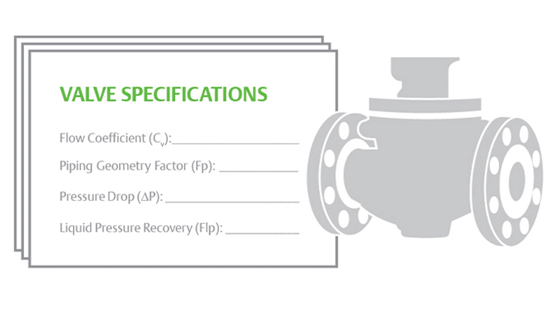
It is important to provide the following information in order to size a control valve properly:
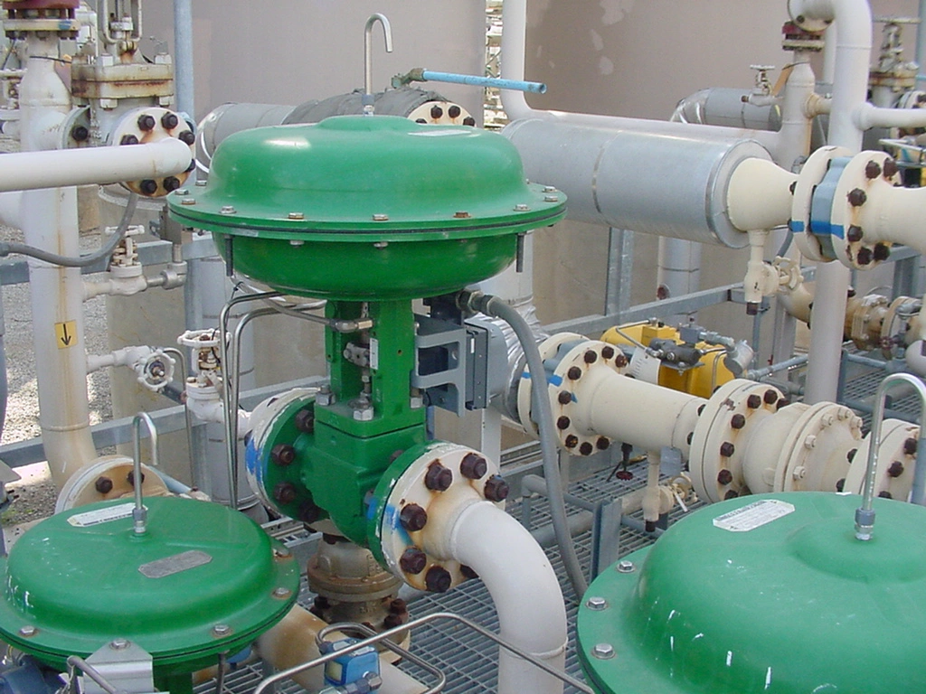
- Physical details (pipe size, pressure class, trim type)
- Process conditions (upstream pressure, downstream pressure, temperature, noise limit)
- Fluid properties (flow rate, density)
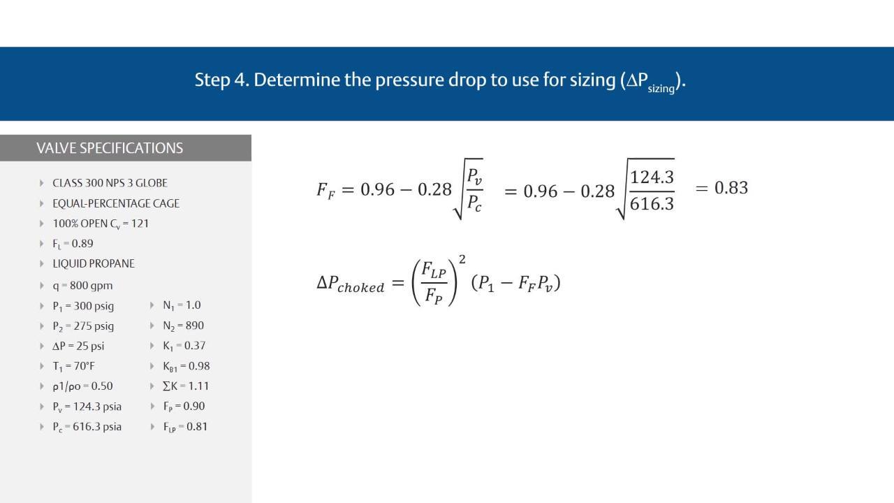
How to Size a Control Valve for Liquid Flow
STEP 1
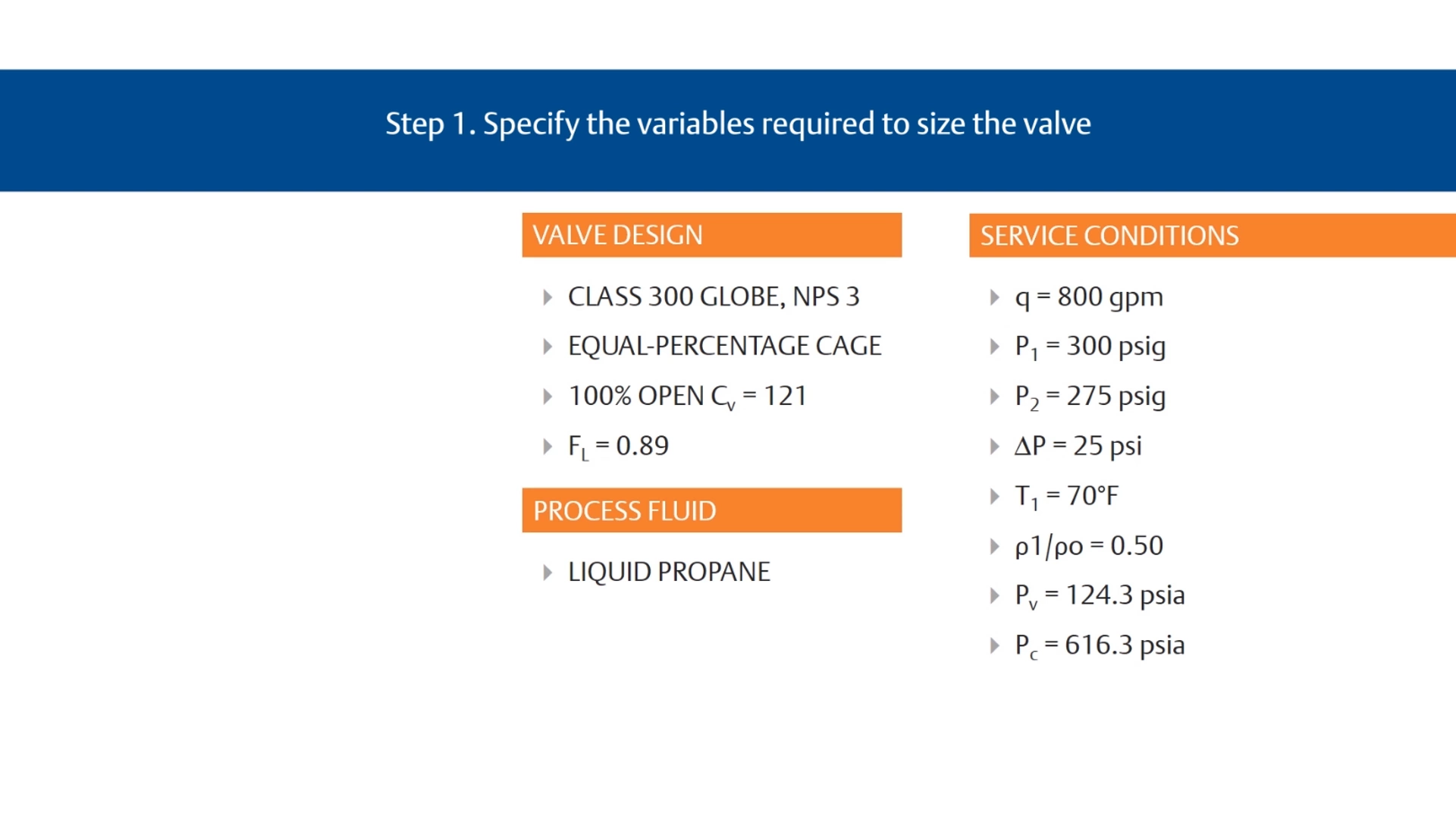
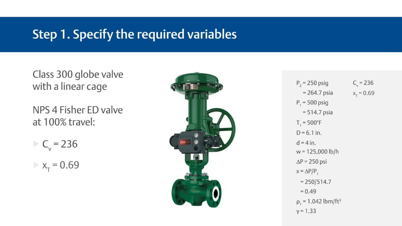
Step 1: Specify the variables required to size the valve
- Desired design
- Process fluid (water, oil, etc.)
- Appropriate service conditions
- q or w, P1, P2 or ΔP, T1, ρ1/ρo, Pv, Pc, and n
The ability to recognize which terms are appropriate for a specific sizing procedure can only be acquired through experience with different valve sizing problems.
Control Valve Sizing Videos
How to Size a Control Valve for Compressible Fluid
Learn the step-by-step process for sizing control valves for compressible fluid using the ISA and IEC’s recommended procedure.
How to Size a Control Valve for Compressible Fluid

Webinar: Control Valve Sizing and Selection - Fisher Technology Quick Talk
Webinar; Control Valve Flow Characteristics
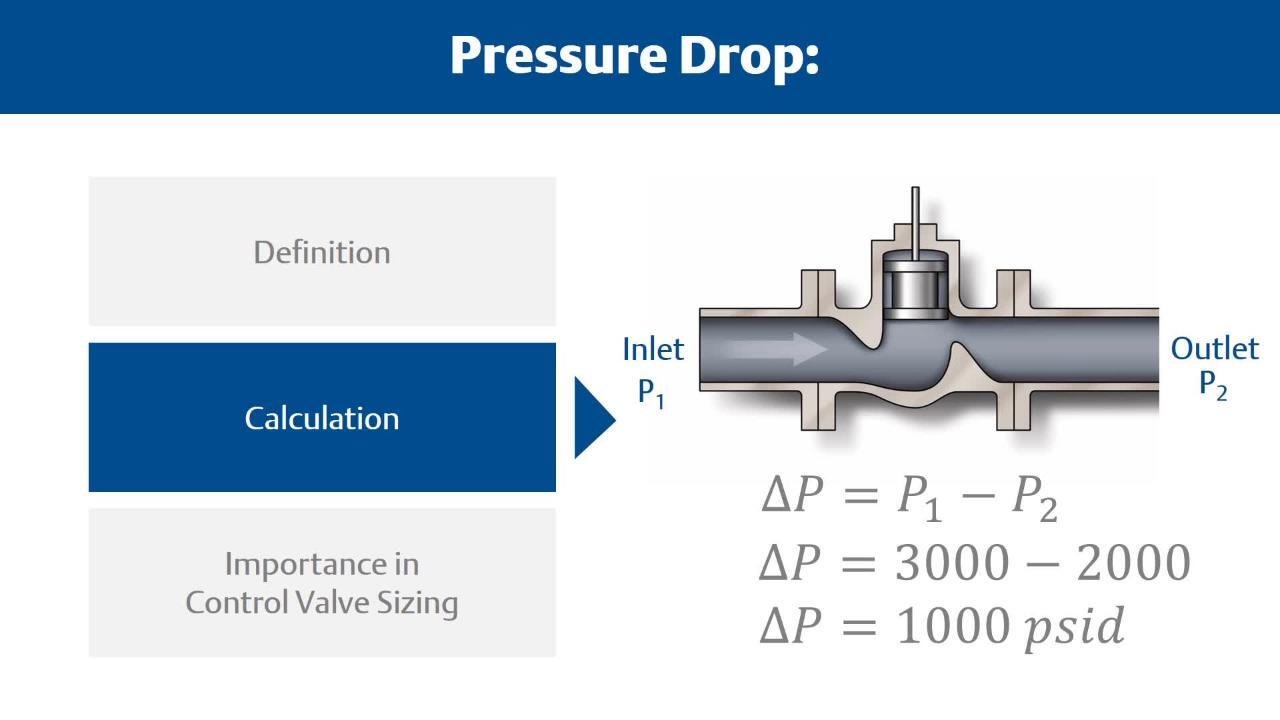
Control Valve Sizing Basics: What is Pressure Drop?