

Application Challenges
- Significant pressure drop
- Excessive noise levels
- Full cryogenic temperatures

Joule-Thomson Control Valve Opportunities
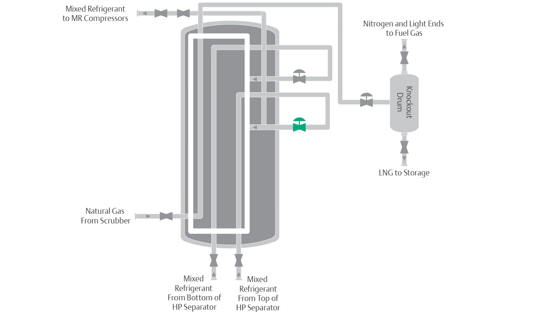
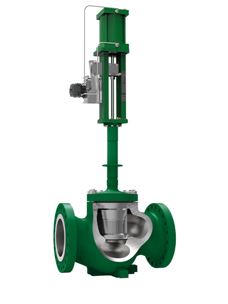
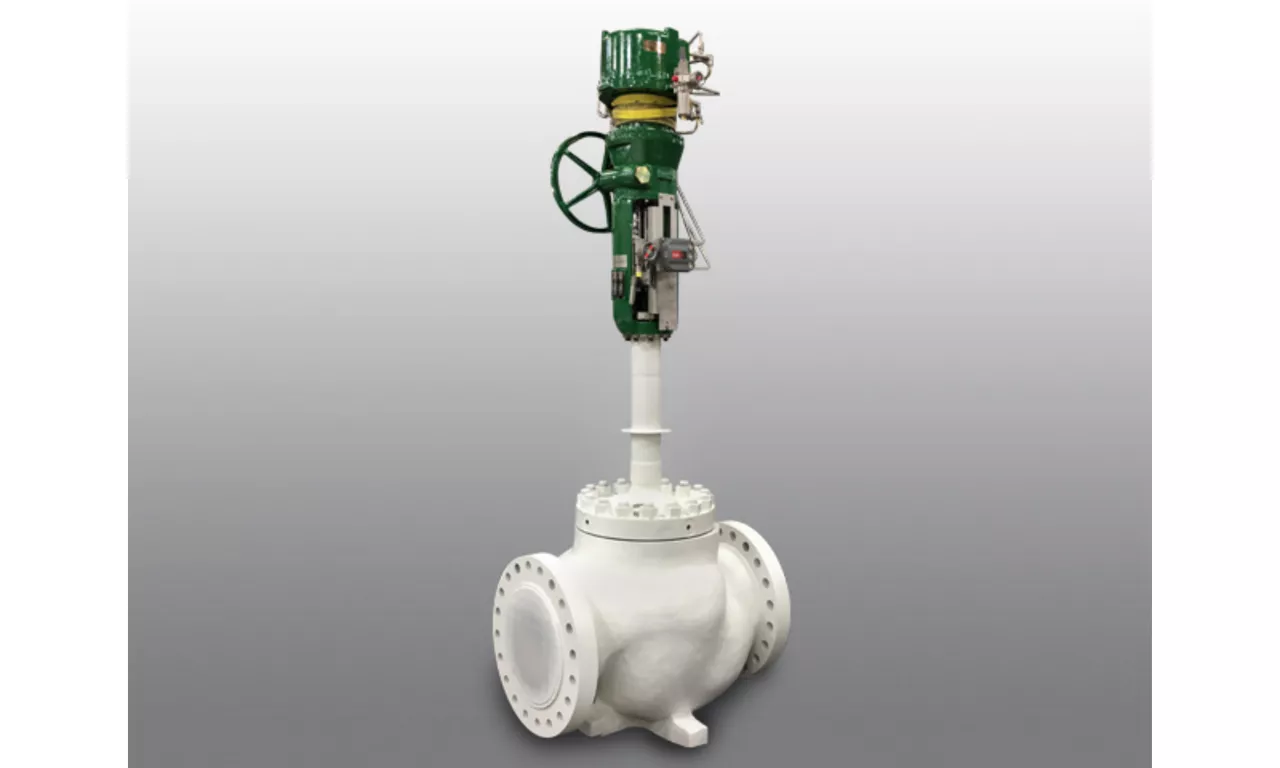
Warm Joule-Thomson Valve
When the mixed refrigerant moves up the tubes between the inlet to the main heat exchanger and the warm Joule-Thomson valve, it loses its heat to the colder mixed refrigerant fluids moving countercurrent through the shell. Therefore, when the mixed refrigerant reaches the inlet to the warm Joule-Thomson valve in the lower section of the main heat exchanger, it is typically at cryogenic temperatures, around −200F (−130C). The mixed refrigerant fluid that flows through the valve may turn into a liquid and vapor mix as it exits the valve. The proper trim must be selected. Balanced cryogenic valves are preferred. If a large percentage of refrigerant by volume is converted to a vapor when the valve takes its pressure drop to spray the bundles, then the drilled-hole or slotted trim in a flow up direction is used to eliminate flashing related noise, vibration and erosion.